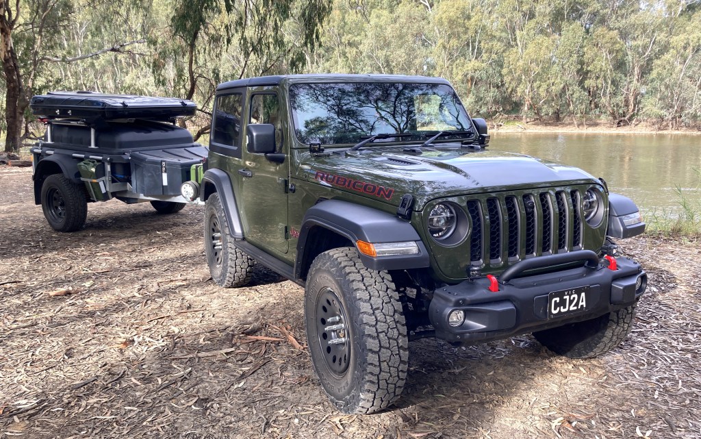
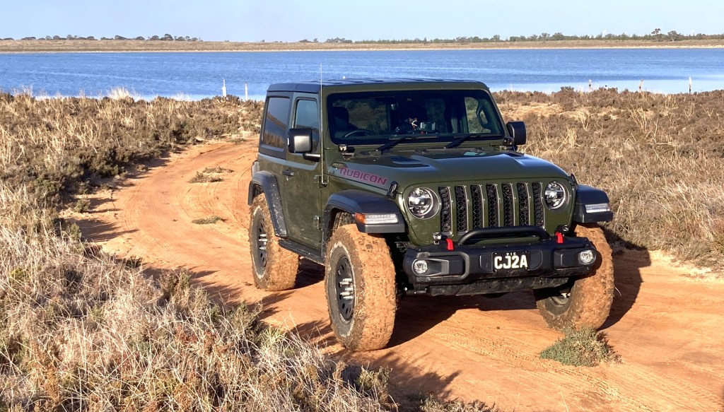
As mentioned in Curb Weight I’m using a 2023 Wrangler JL Rubicon 2 Door as my base vehicle. Without going into a lot of detail about its characteristics, it is probably the most capable off-road vehicle available off the showroom floor in Australia. So there isn’t much development required to get it prepared for overland expedition use. In fact many sources suggest that the majority of failure in overland vehicles comes from owner installed after-market options, so to minimise the expense and effort I’ll only be changing what is necessary.
Reverting Australian “Nerfs”
To comply with Australian regulations Jeep have made a few Nerfs to the specification for the Rubicon. These include fitting “low-rider” front guards, and most importantly fitting very small tires (equivalent to those delivered on the Sport and Sahara models). There are a few other shortcuts that need to be remedied too.
Tire Nerf
The Wrangler JL was developed to support 35″ tires in the Rubicon X model, and is delivered in the USA with 33″ LT285/70R17 tires. Yet in Australia it is delivered with LT255/75R17 tires. This directly costs 25mm of ground clearance (under the differentials), and affects entry, exit, and break-over angles.
So we’ll specify a new tire closer to the USA Rubicon X OEM specification, but more appropriate for overlanding, with the following characteristics.
- Rugged Terrain (All Terrain) tire
- Light Truck (LT) load specification
- 3 ply side wall
- 3PMS Severe Weather Rating
- 2:1 tire to wheel diameter ratio
- Not wider than 10″ (255mm) – minimise mud throw – reduce rolling resistance – not attract Police attention
- Reputable manufacturer
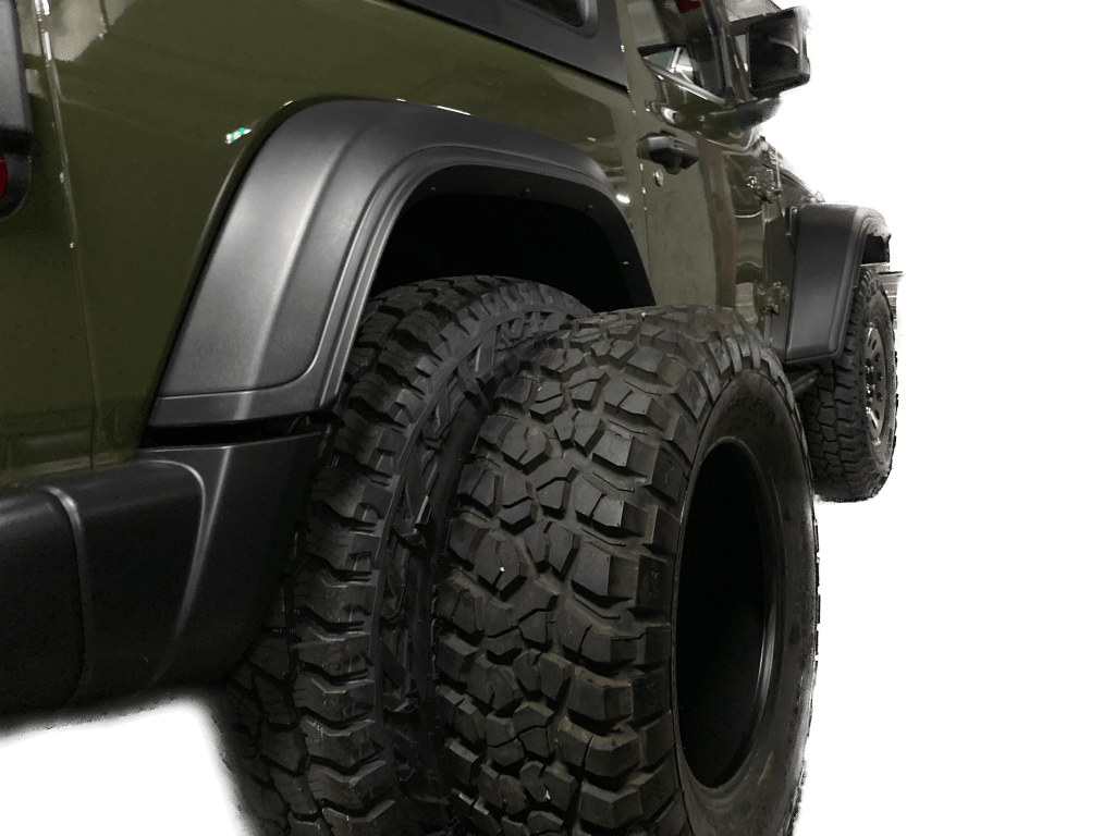
Based on the above specification the best (and only) option is the Mickey Thompson Baja Boss A/T in LT255/85R17. Since the diameter of these tires is just under 35 inches (they are also specified as 35×10.0R17LT), it is likely that the OEM suspension on the Rubicon will need extended bump stops to prevent rubbing on the “low-rider” front guards. Fortunately Teraflex produces a bump-stop extension kit which reduces the upward travel by just over 1″, which is enough to prevent rubbing.
As an option, the Kenda Klever R/T KR601 and Kenda Klever M/T2 KR629 are available in 35×10.5R17LT and they also qualify based on my above requirements. The 35×10.5R17LT size is slightly larger than the LT255/85R17, being a true 35″ tire, and would therefore provide greater ground clearance.
The tires are mounted on Mopar Winter Wheels from the Wrangler JK range, supplied on special order from Jeep Australia. These wheels are the same width and offset as the originals, but protect the valve stem much more and seem more robust than the alloys supplied as standard. The Winter Wheels will fit all the Wrangler JL trims, but not the JT as the Gladiator rear disk rotors are too large to fit inside the wheel.
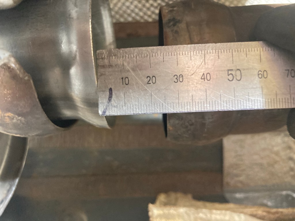
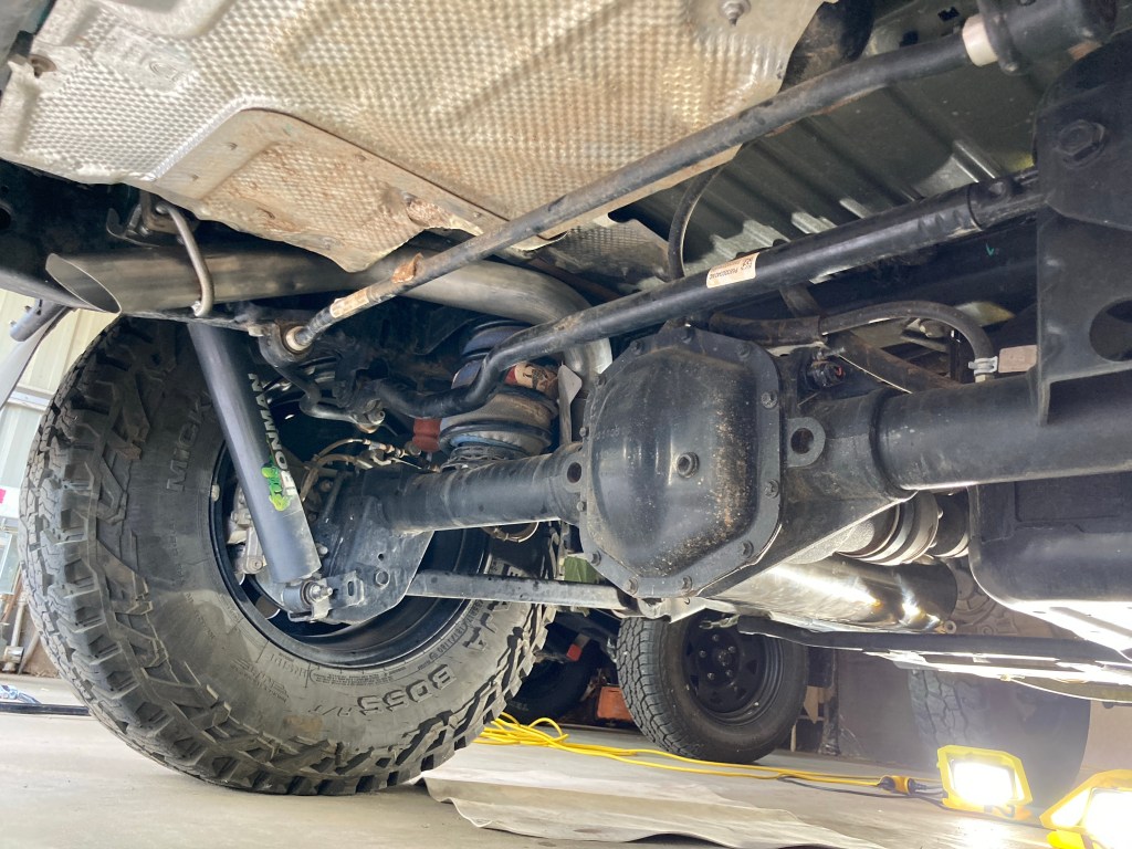
Steering Damper Nerf
When converting the Wrangler JL to Right Hand Drive Jeep placed the steering damper under the track bar (panhard rod), causing it to be a full 50mm under the lowest point of the suspension. Owners who take their Wranglers off-road always damage the steering damper and it can get hooked up on the large attachment point hanging under the front axle.
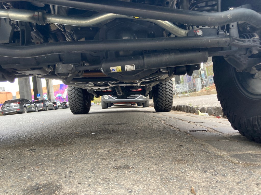
The recommendation is to use a Teraflex steering damper relocation kit to move the damper above the drag link and out of the way of harm. Together with the relocation kit it is necessary to add an aftermarket steering damper. The brand doesn’t matter too much but for the record, I used an ORV Rugged Ridge steering damper originally for a JK Wrangler.
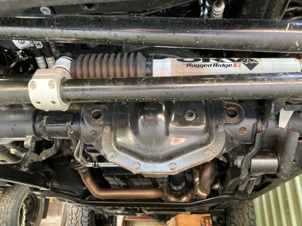
After relocating the steering damper, the large mounting point hanging under the axle can be cut off with an angle grinder / cutter. With a fairly neat set of cuts about 2kg of metal comes off the front axle which improves ground clearance and helps with reducing unsprung weight.
Rubicon Caster Reset
The Wrangler JL Rubicon is lifted by over 1″ over its sister models. This provides the space for larger tire sizes, but in doing the lift Jeep did not rework the control arms to retain the designed front wheel caster.
Specifically the JL Sport and many other cars use over 6 degrees of caster to stabilise the steering. Caster also has the positive side effect of improving cornering by increasing the steering angle of the tires. However, after the OEM JL Rubicon lift is fitted the resulting caster is only about 4.5 degrees.
Fortunately Mopar produces an extended front lower control arm which is 1/4″ (6mm) longer than the standard length lower control arm. This was produced as part of its Mopar 2″ lift kit. Fitting these extended lower control arms returns the front wheel caster to 5.5 degrees. This quietens the steering and makes the driving experience much more relaxed.
Suspension Improvements
Noted above are the extended front lower control arms and the extended bump stops, so the only additional improvement is the addition of heavy duty shock absorbers (dampers). The majority of protection required will be on corrugated roads, where the suspension travel is minimal and high frequency. This means that external reservoir dampers, which are designed for long travel situations (like a Baha race) are not the best solution. For the Australian outback I have selected to use the Ironman 4×4 Foam Cell Pro dampers. These dampers are the traditional robust twin-tube design (not pressurised), built with huge oil reserves and very solid (rebuildable) construction. It is also worth noting that they extend the axle droop by over 2″ over the standard dampers, as they are specified for a 2″ lift kit. The extended droop makes both axles more compliant to the terrain, and more than compensates for the reduction in upward travel through the extended bump stops.
As the ball weight of my trailer combined with the load of equipment will add about 260kg to the rear of the vehicle, it is necessary lift the rear when fully loaded and yet allow the full travel and comfort when the vehicle is used for rock crawling day trips. The ideal solution for this is to use Air Bag suspension assistance, which allows adjustable support up to 400kg. I’ve fitted AirBag Man Heavy Duty airbags and run them at 40 psi to 45 psi when towing and 5 psi when not.
Towing System
The Wrangler Rubicon has a very light weight plastic rear bumper bar. The OEM tow bar is fitted underneath the bumper on a chassis cross member with 4 high tensile steel bolts. The rear recovery hook is bolted to the chassis with 4 high tensile bolts.
To provide a solid towing and recovery platform the rear bumper and hook were removed and a Smittybilt XRC Gen 2 rear bar was fitted. This bar is bolted to the chassis with 12 high tensile steel bolts, 4 in the normal OEM tow bar location, and 4 at each chassis rail. The bar itself weighs over 48kg, and provides a Class 3 Receiver and two recovery and high lift jack points.
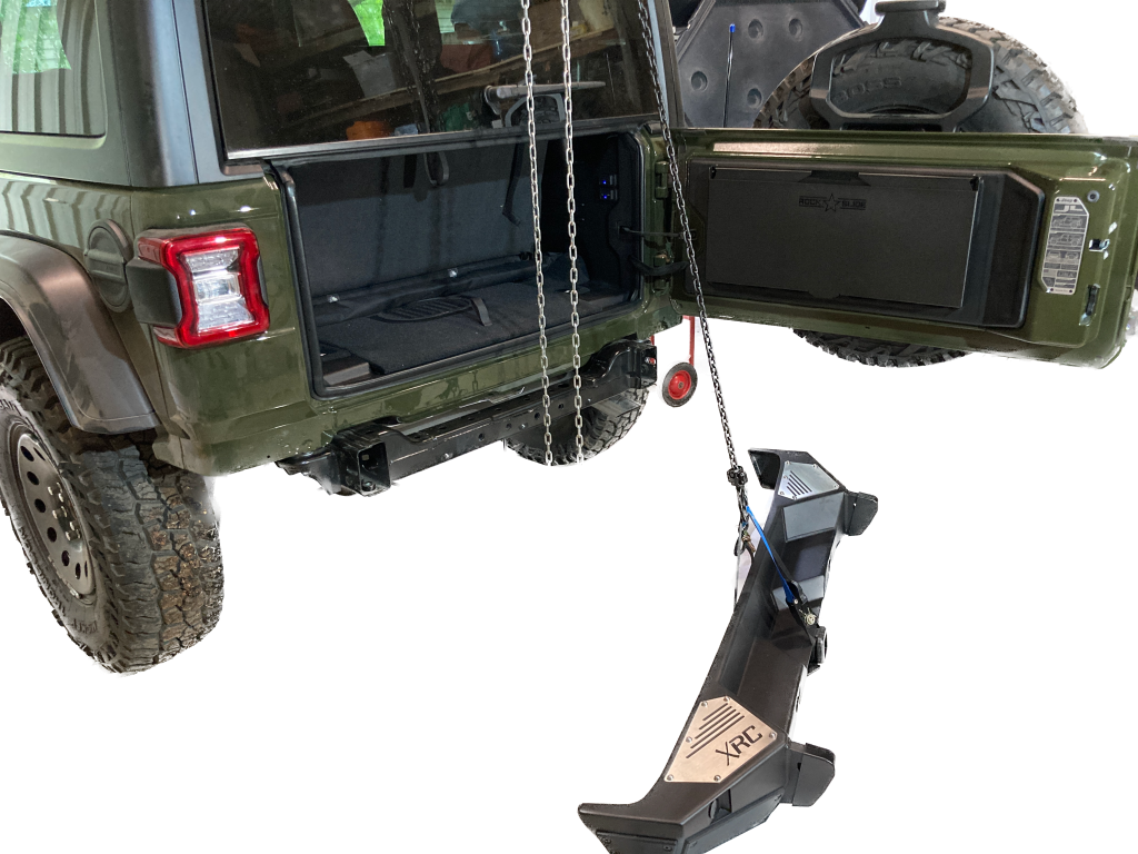
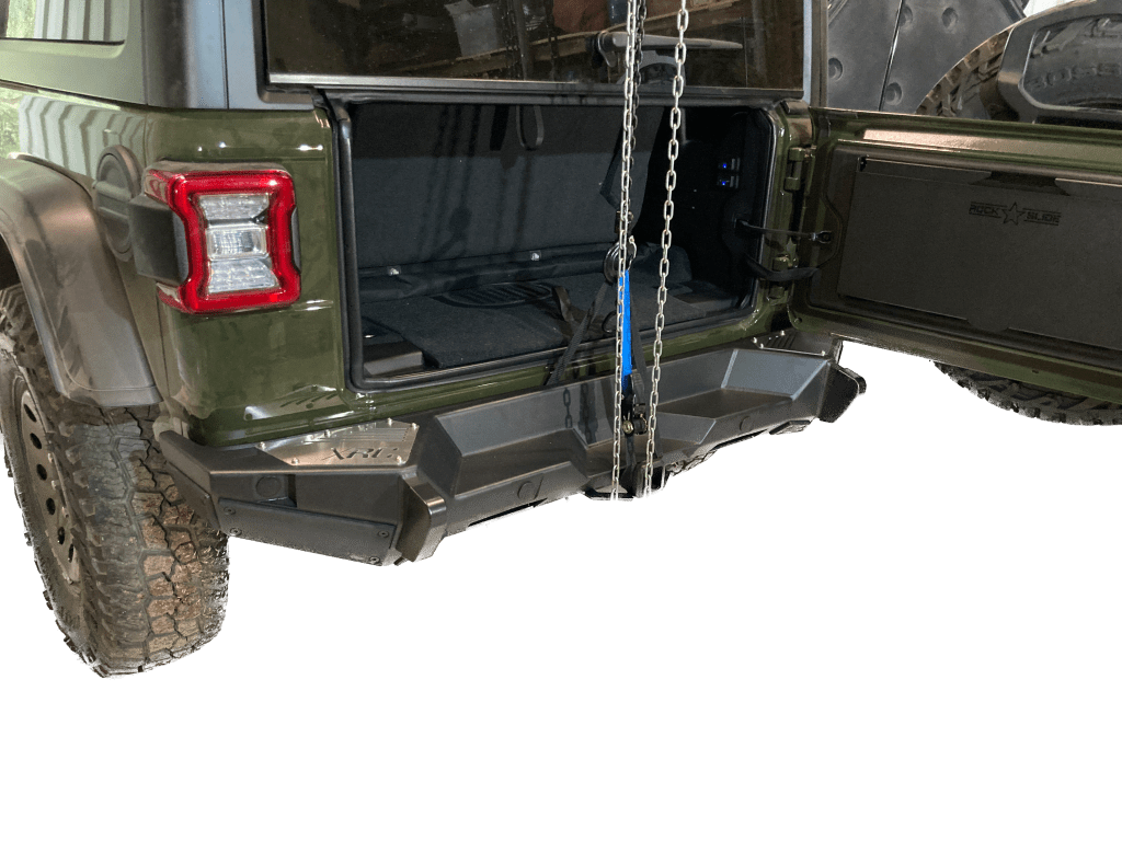
Removing the OEM rear bumper necessitates relocating the number plate. The relocation was done with a combination of the included Smittybilt product and an ARB number plate relocation kit.
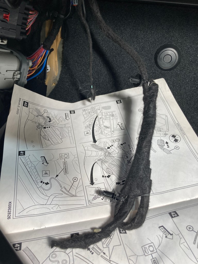
Trailer wiring for Australian (APAC) vehicles is different to the American (NAFTA) solution. The NAFTA Jeeps do not have a separate brake and indicator system; their brake light is flashed as an indicator. So purchasing a NAFTA Trailer Wiring System is not going to work. The best solution is the purchase the Australian (APAC) Trailer Hitch kit (MOPAR Part Number LA82210162) directly from a dealer. The Australian Trailer Hitch kit includes a 2″ drop tongue, 50mm ball and Australian 7 Pin Flat Trailer Connector, as well as an OEM hitch point (which I have not used).
The international Trailer Brake Controller (MOPAR Part Number 82215652AD) kit works well with the Australian Trailer Hitch kit. The control knob fits nicely into the dash, replacing the 12V cigarette plug, and the ECU can be stuffed up into the space behind the panel in the passenger footwell.
Fitting the Australian Hitch kit meant passing the trailer wiring INSIDE the vehicle (like the Quadratech video) not outside according to the instructions and routing the wiring through dash behind the ICE head unit and down into the LHS (passenger) footwell to mate with with the Trailer Brake Controller and its wiring.
The accessory wiring and Trailer Brake signal wire are both found in the LHS footwell. From the LHS footwell the power supply for trailer lighting and trailer brake can be (optionally joined to one supply and) passed through the firewall into the LHS front wheel well and so to the battery.
Other Things Worth Mentioning
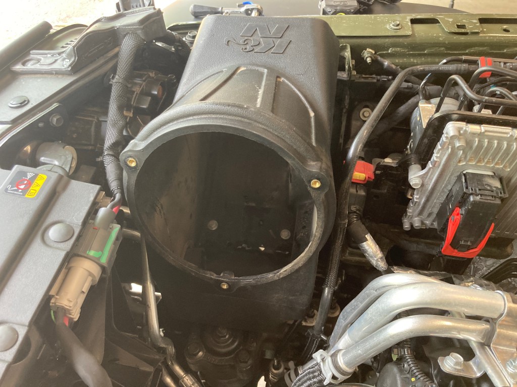
Cold Air Intake
Added a K&N air box and filter kit, and integrated the OEM cold air intake into the bottom of the K&N air box by cutting off the curved end of the CAI and cutting a matching hole in the side of the K&N air box. As the K&N filter can be easily cleaned and renewed anywhere, it is ideal for use in dusty outback conditions.
Taser JL Tuner
A Taser JL Mini allows the tire size and many other settings to be done at any time. It also provides live info on the manifold vacuum and does light shows when needed.
Interior
I’ve added a GME UHF radio in the centre console, connected to a 6.6dB elevated feed spring mounted antenna on the tail-gate. There is a Teraflex tail-gate mount for both antenna and sand flag.
Upgraded the audio system’s front loud speakers with Terra Acoustics JL Sound Stage.
Fitted Rubicon 392 Gear Shift Paddles to steering wheel. Very useful off-road, for keeping both hands on the wheel.
Also on the tail-gate there is a Rockslide Engineering table, and some additional 12V connectors and USB connector power supplies.
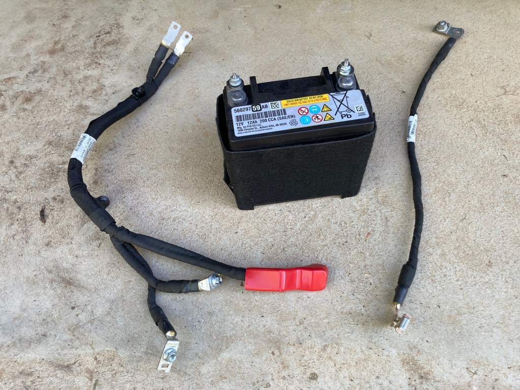
ESS Battery Delete
I’ve removed the small 12V ESS auxiliary battery (saving over 5kg), and all associated wiring, leaving just the disconnected PCR relay signal wires in place to ensure there are no ECU codes generated. Bridging N1 and N2 in the power distribution centre ensures that normal service for all power systems is retained, even the ESS function (although I keep ESS switched off).
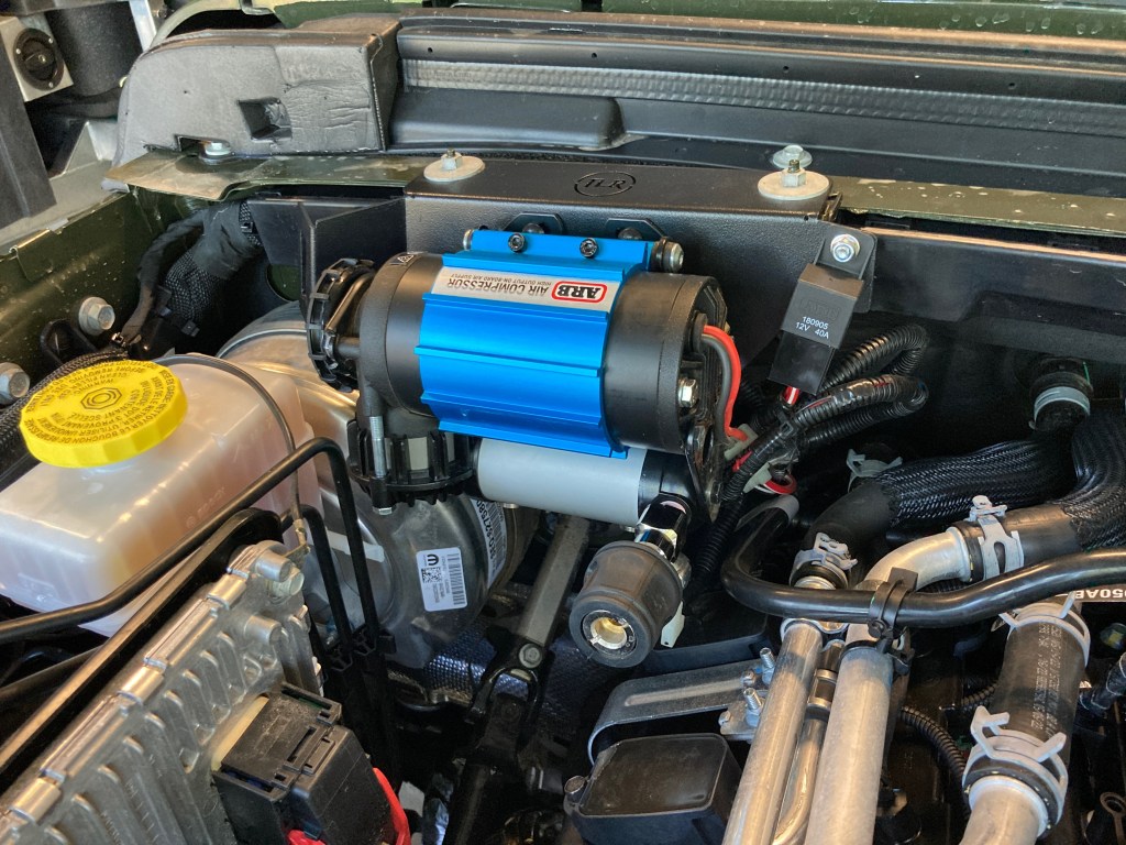
Air Compressor
An ARB air compressor is fitted in the engine bay with a RHD specific mount from TLR.
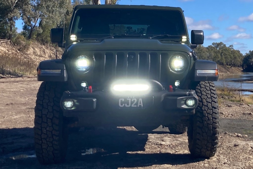
Front Lighting
Added front lighting to; 1. Provide around corner trail and work cube lights to A-Pillar mounts. 2. Improve spread and range of fog lights with letter-box lights. And 3. Enhance high beam fill with a spot bar. Each of these light improvements are modest, and importantly being small they don’t block airflow to the engine or transmission radiators.
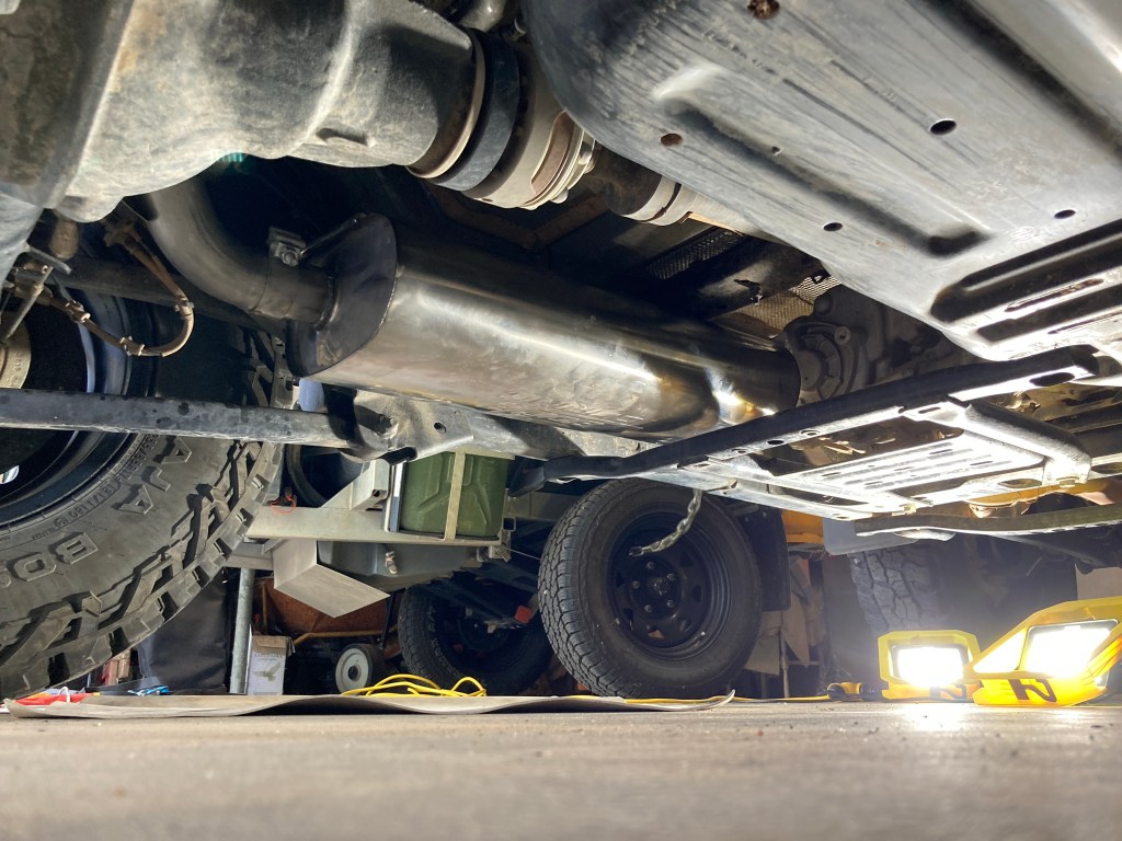
Exhaust System
Added a Borla Climber exhaust in the Touring version. This exhaust moves the muffler forward of the rear axle to increase departure clearance (though the rear bumper still determines the ultimate departure angle). The Climber exhaust system is 7kg lighter than the OEM exhaust and moving all the muffler weight forward of the rear axle is a useful result.
Interestingly, fuel economy also seems to be substantially improved, probably because the straight-through Borla Climber muffler is reducing cylinder back pressure. On a standard journey (of known distance and speed), improvement by over 1.5l/100km was posted, off the OEM base economy of 12l/100km.
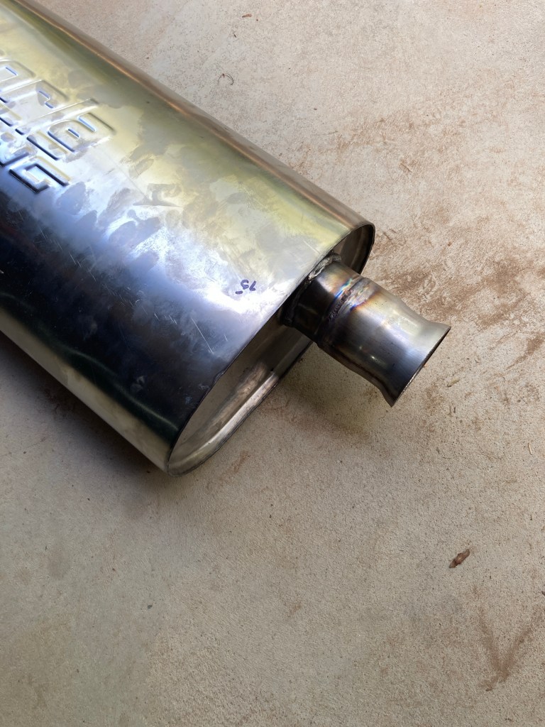
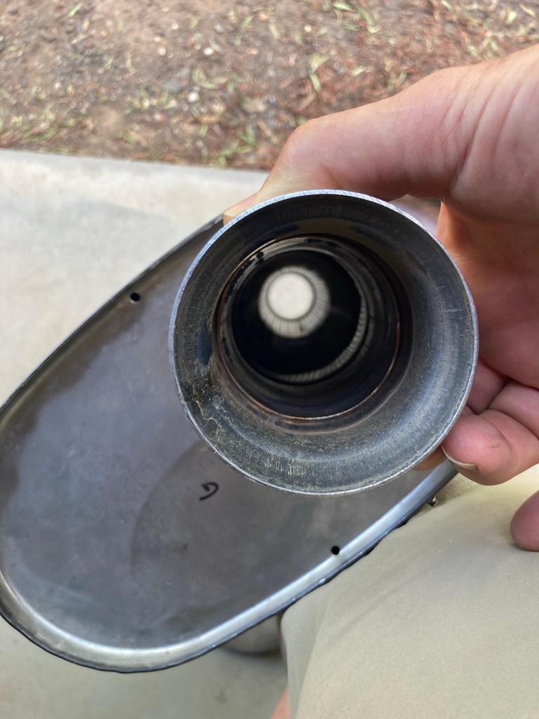
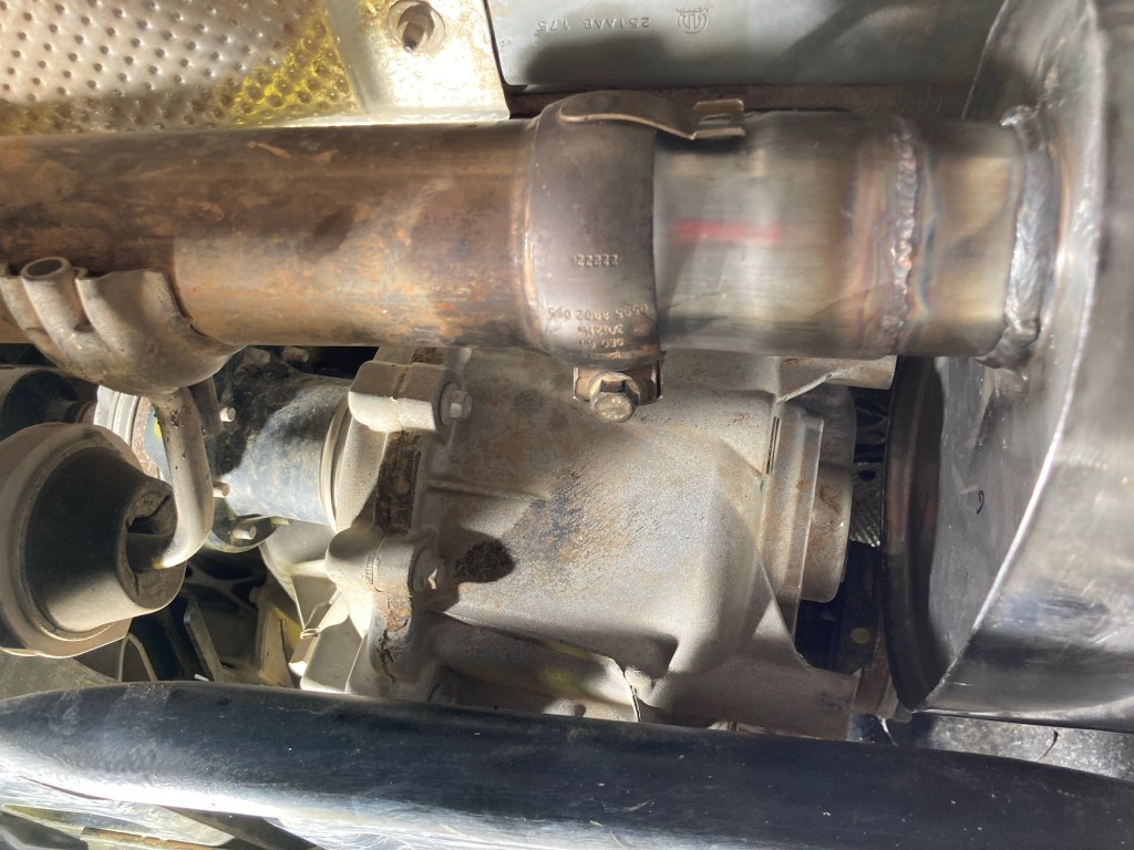
Unfortunately the 2DR version of the Borla system doesn’t fit the Rubicon RHD version precisely, and the muffler needed to be relocated 35mm to the rear to clear some protruding sections of the transfer case housing. This was done by extending the muffler front pipe and shortening the tailpipe flange, each by 35mm.
Regearing and TORSEN Differential
Recently, I’ve regeared the differentials to 4.88:1 which helps to run regularly in 8th gear when towing. Now 100km/h is set to 2,000 RPM in 8th, or 2,500 RPM in 7th if it is hilly. The overall lowest crawl ratio becomes 93:1, and this changes normal 20 deg plus hill ascents to 4th or 5th Low Range. This adds substantial flexibility in choice for climbing gears and crawling technical tracks.
Lastly, I’ve swapped the rear Jeep eLocker differential for a TORSEN differential. More in this post.
Karl (of Karl’s Diffs) did both TORSEN and regearing installations. Both installations had their quirks and took longer than expected, and so are best done by experts, like Karl.