
There’s a great new Arduino Uno (pre-R3) Shield available from Open Music Labs. Their Audio Codec Shield is an Arduino shield that uses the Wolfson WM8731 codec. It is capable of sampling and reproducing audio up to 88kHz, 24bit stereo, but for use with the Arduino it is practically limited to 44kHz, 16bit stereo. The Audio Codec Shield has 1/8″ stereo input and headphone output jacks, a single pole analogue input aliasing filter, and 2 potentiometer for varying parameters in the program on the fly.

The Open Music Labs provides a some libraries and code examples for use with the Arduino IDE, and also with the Maple IDE. But, rather than just use the existing code, I thought it would be fun to develop some freeRTOS libraries from their basis code.
I spent quite some time understanding exactly how the WM8731 worked, and what was needed to make it perform, in a RTOS environment. It is clear, that to work at the audio rate of 44.1kHz, that the Arduino needs to be clocked by a hard interrupt, rather than by a soft timer. So, I spent some time designing and playing with different methods of driving the board.
Initially, I thought it would be good to limit the interrupt processing to constant clock in and clock out of data, that MUST happen every sample (at 44.1kHz) or the sound sampling or playback is simply broken, and allow the interrupt to semaphore a further processing task to wake it up. However, once I understood just how limited the time available is for processing, it became apparent that (at least for the 16MHz Arduino) there is no time left to muck about with a RTOS, and everything has to be kept as simple and regular as possible.
Never the less, the freeRTOS code is useful to provide serial and I2C libraries to set up the board, and possibly to do some other tasks where possible.
The resulting code consists of just one freeRTOS Task, that initialises the Shield, and then suspends itself indefinitely. The freeRTOS Scheduler keeps on running, but finding no available task will just pend itself until its next timer tick.
  AudioCodec_ADC_init();    // initialise the potentiometer sampling.
  AudioCodec_SPI_init();    // initialise the SPI bus for special purpose Audio Codec use.
  AudioCodec_init();        // initialise the Audio Codec using I2C bus.
  AudioCodec_Timer1_init(); // set up the sampling Timer1, runs at audio sampling rate.
  vTaskSuspend(NULL);       // well, we're pretty much done here...
First the Arduino ADC is initialised into free running mode, to provide inputs from the two potentiometers on the Shield. The Open Music Labs have provided an analysis of the Arduino ADC, and they show that the free running mode provides the lowest noise floor. Not that it is important to have a low noise floor for this purpose, as it is just potentiometer sampling. However, they missed the trick of using decimation to improve the sampling resolution, choosing instead to use a dead-band for the sampling. I’ve changed the ADC initialisation to do variable sample decimation, depending on the bit depth desired.
This is the example code for a single potentiometer.
static inline void AudioCodec_ADC(uint16_t* _mod0value)
{
  if (ADCSRA & (1 << ADIF))     // check if sample ready
  {
    _mod0temp += ADCW;  // fetch ADCL first to freeze sample is done by the compiler
    ADCSRA = 0xf7;      // reset the interrupt flag
    if (--_i == 0)      // check if enough samples have been collected
    {
      _mod0temp >>= DECIMATE;   // Decimate the summed samples
                                // (to get better accuracy), see AVR8003.doc
      *_mod0value = _mod0temp;  // move temp value to the output
      _mod0temp = 0x0000;       // reset temp value
      _i = _BV(2 * DECIMATE);   // reset loop counter
    }
  }
}
Then the SPI bus is configured to sample the data from the ADC on the WM8731, and to write data back to the DAC. Since we’re using the DSP interface, which is very similar to the SPI bus interface, with 16 bit transfers, the SPI mechanics can be used effectively, removing the need to bit-bang the interface. I found that although SPI Mode 0 nominally looks to be correct, it would lose the most significant bit of most transactions, being the left channel input values. I needed to use Mode 3 to get effective transactions.
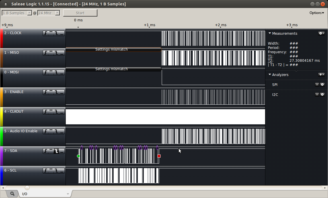
The I2C bus is used on pins A4 and A5, which is pre-R3 format. I would digress to say that decision not to continue to support the SDA/SCL pins being available on A4 and A5 is a very bad one, in my opinion. There are many old, and this quite new, Shields that will simply be broken by this decision. Simply, bad for the Arduino legacy.
I have completed the register and pin definitions in the header file, to allow simple selection of the configuration, by adding the appropriate bit values into the register settings.
The initial I2C command transaction looks like this.
Here is a bit more detail on the DIGITAL_PATH_CONTROL command.

The true heart of the project lies within the use of Timer 1 to signal the 44.1kHz timing required to produce the sound samples. An interrupt driven by the Timer 1 counter signals the transfer of data, performing any audio processing required on the incoming data, and writing it to the output ready for the next transfer, and sampling the analogue potentiometers to use them as as mod inputs on the signal. The Timer 1 counter is incremented by counting the CLKOUT line coming from the Shield.
ISR(TIMER1_COMPA_vect)
{
  // WM8731 data transfer routine
  // move data from and to the WM8731 - done first for regularity (reduced jitter).
  AudioCodec_data(&left_in, &right_in, left_out, right_out);

  // audio processing routine - do processing on input - prepare output
  AudioCodec_dsp();

  // adc sampling routine
  // sampling the potentiometers (no sound here)
  AudioCodec_ADC(&mod0_value, &mod1_value);

  // end mark - check for end of interrupt - for debugging only
  PORTD |= _BV(PORTD6);   // Ping Audio Shield buffer line.
  PORTD &= ~_BV(PORTD6);
}
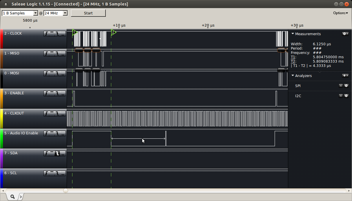
As I noted above, timing is everything. Based on the plots below, it takes exactly 6us for the AudioCodec_data() function to transfer the data from and to the WM8731. This doesn’t seem like very long, but to maintain a sample rate of 44.1kHz, each transaction must be completed in less than 22.7us, as shown below.
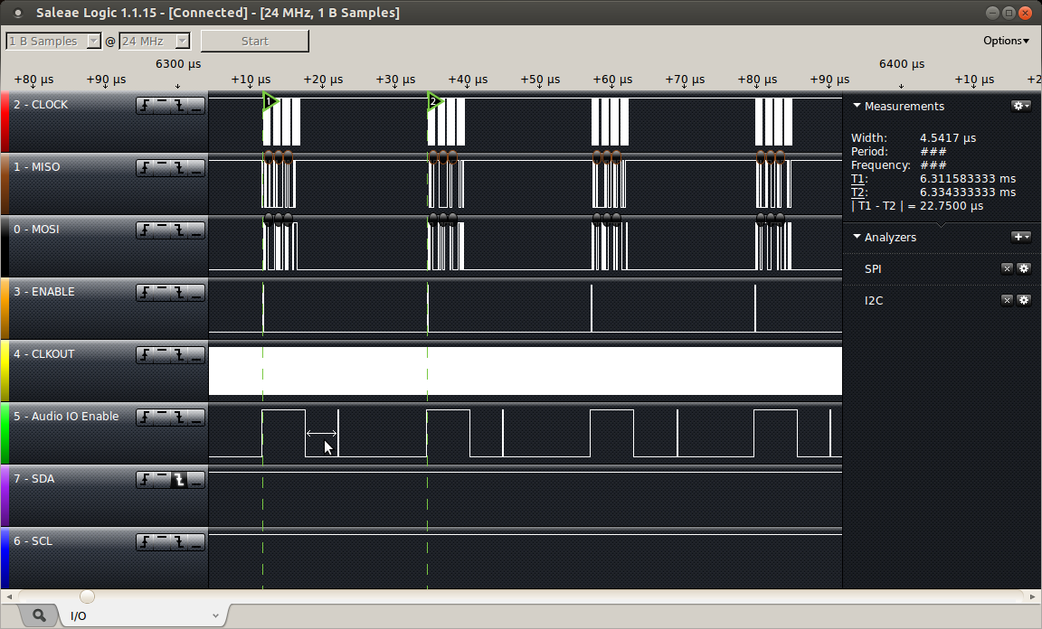
The logic trace below shows the situation with the simplest AudioCodec_dsp() function available. Here the DSP processing is completed with over 15.7us to spare. The actual AudioCodec_data() function takes exactly 6us to complete (T1-T2), and can be used as a scale for other logic traces below.
inline void AudioCodec_dsp(void) // straight through connection I-O
{
  left_out  =  left_in; // put in to out on left channel
  right_out =  right_in; // put in to out on right channel
}
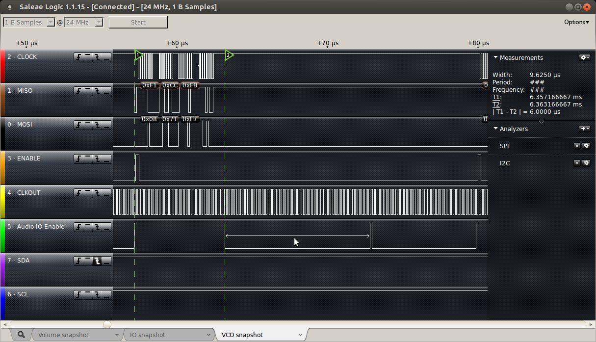
Other more complicated routines, such as a sine-wave Voltage Controlled Oscillator (digital of course) take a little more time from our limited budget, needing 9.6us to complete.
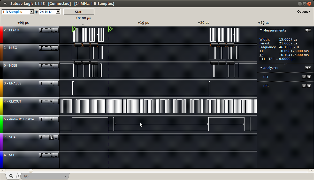
I have used the same code on a Freetronics Eleven, an Arduino Uno clone, overclocked to 22.1184MHz, and as can be seen below, it results in the AudioCodec_data() function taking 4.33us (vs 6us standard) and the VCO code taking 6.125us (vs 9.6us standard). Whilst these savings are relatively small, by comparing the two logic traces, I think they do change the result enough to make it worthwhile for this application.
Code is as usual on Sourceforge in avrfreeRTOS.
In further work, I will build some useful DSP programs from the examples provided, such as a reverb or flanger filter.
UPDATE
After reading this article on the MicroMonsterModular I’m going to play with adding some new sequences.
This WurstCaptures web site can help to build them quickly, and CounterComplex has a few ideas too.
output = t * (t >> (pot1>>4) | t >> (pot2>>4) )&((pot3>>3) + 16)
output = (t * (( t>>9 | t>>13 ) & 15)) & 129
output = (t * (t>>8 + t>>9)*100) + sin(t)
output = t * (((t>>12)|(t>>8))&(63&(t>>4)))

Pingback: Elekit TU-879S Stereo Valve Amplifier Kit Review | feilipu
Pingback: Goldilocks Analogue – Testing 3 | feilipu