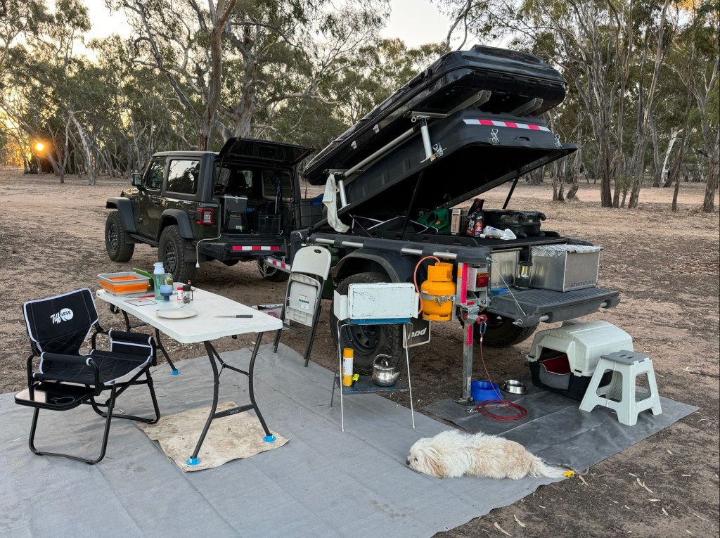
My Stockman Pod Extreme has worked very well across a range of on-road and extreme off-road situations. But recently I upgraded the Cruisemaster XT Freestyle suspension to better suit the operating weight of the Pod.
Usually I drive quite conservatively with the Pod, as all my required camping equipment is stored in the internal drawers and there is no reason to shake it up. But recently, while driving quickly to outrun a storm, I noticed that the suspension on the Pod Extreme was not working effectively.
Gross Vehicle Mass
The Stockman Pod Extreme has a Tare Weight of 440kg and is rated to a maximum GVM of 1250kg.
Usually I don’t carry over 800kg of load on the Pod which would reach the maximum GVM. I believe that the total operating weight of my Pod is actually around 950kg, which is well short of the maximum GVM.
It might seem like very little difference between my actual operating load and the GVM, but in practice it means that the springs are substantially stiffer than are really necessary to work at the operating load of less than 1000kg.
So why doesn’t Stockman specify a lower rated system for the XT Freestyle suspension fitted? This is because there is no lower weight rated option available from Cruisemaster, so they’re already using the lightest specification available.
XT Freestyle Spring Specification
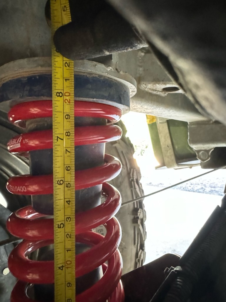
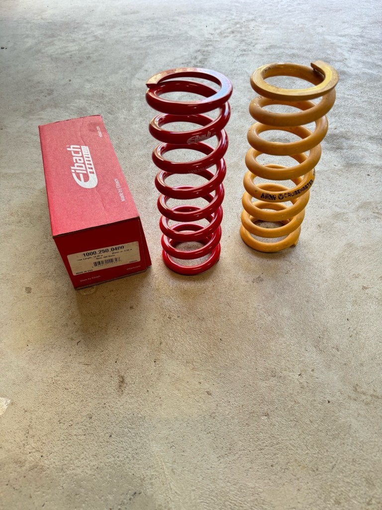
A little research (calling the spring manufacturer, King Springs) reveals that Cruisemaster use a standard design “coil-over” spring in their XT Freestyle systems. The key measurements are a spring free height of 10” and an internal diameter of 2.5”, with ground flat ends.
A few years ago King Springs stopped making coil-over springs in their Kings Performance Springs (KPS) range, hence Cruisemaster now special orders its XT Freestyle springs. So we can’t use King KPS springs as an option.
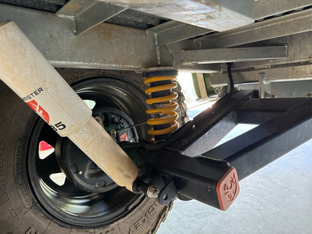
As noted the lowest rated spring option available from Cruisemaster is for a GVM of 1200kg. This rating is created by using 550lb per inch springs. This figure is noted on the screen printed serial numbers on the existing Cruisemaster XT springs.
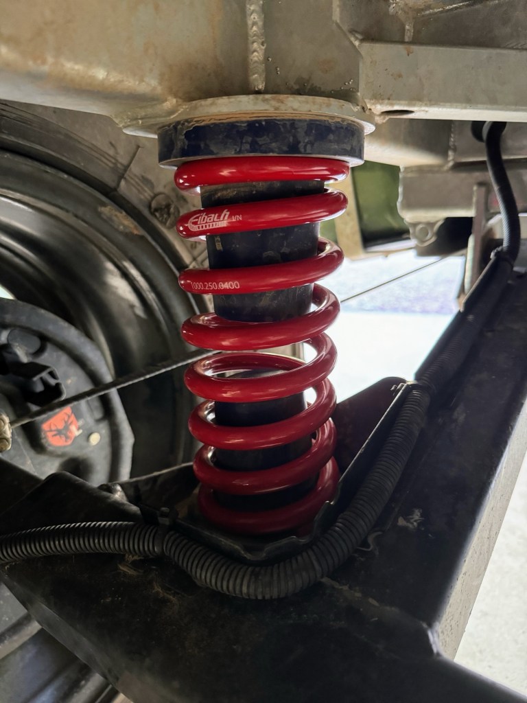
Cruisemaster XT Freestyle with 550lb Springs
Calculating Optimum Spring Rate
As noted the operating weight of my Stockman Pod is around 950kg. This is based on a) calculating the aggregate weight of the contents, and b) measuring the existing spring deflection.
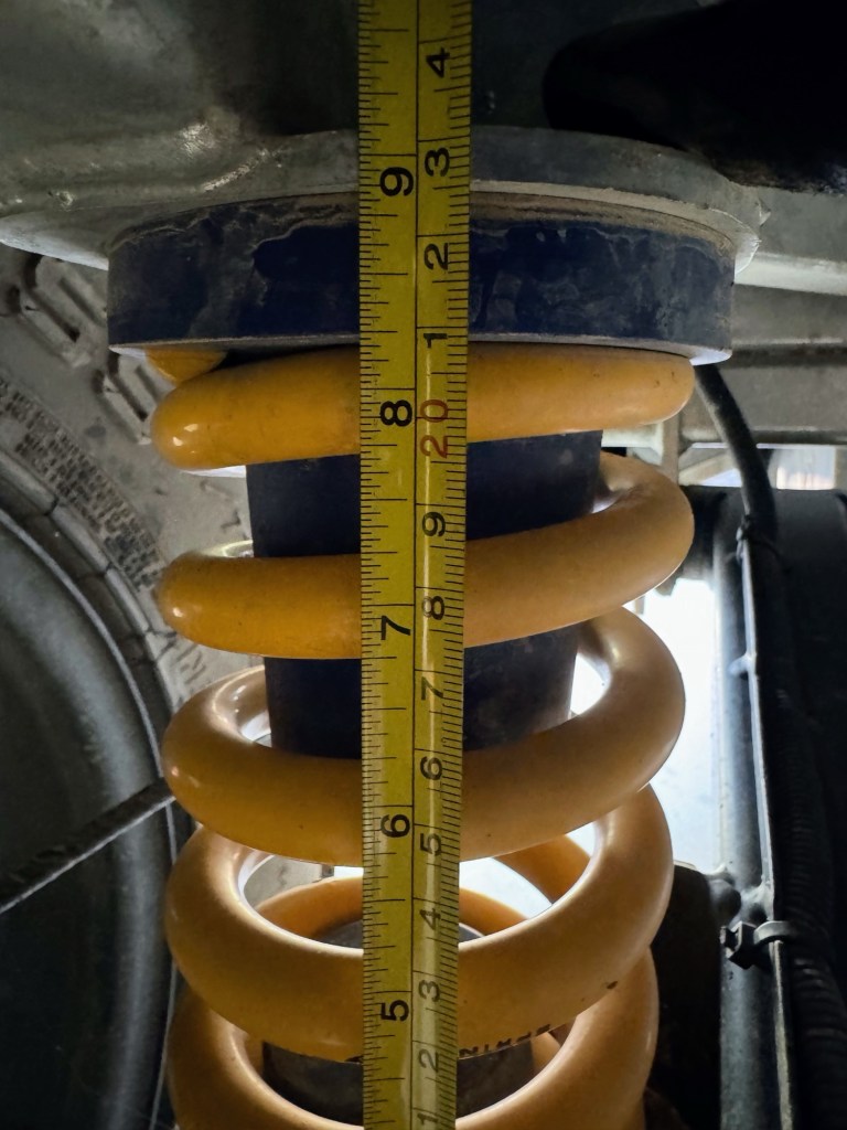
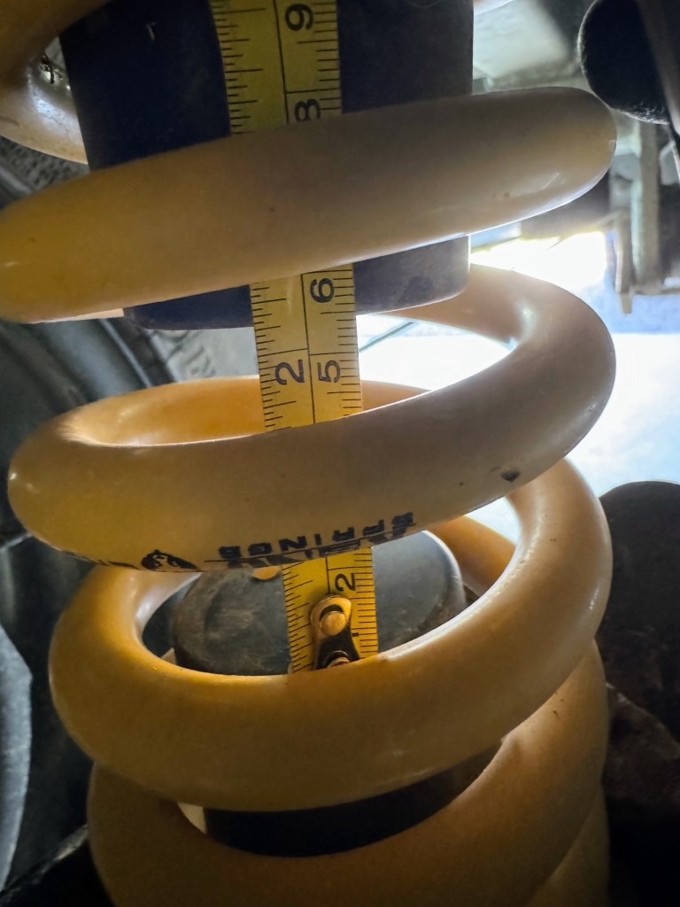
The existing spring deflection is about 40mm under operating load, with the spring being about 210mm at rest. There is about 55mm of clearance between the bump stops.
Using this information, it is possible to calculate what the full load deflection of the spring should be, and then to calculate what the spring rate could be reduced to, whilst keeping actual deflection less than the standard full load deflection.
For my operating weight of 950kg, it would seem that the ideal spring rate is about 400lb per inch.
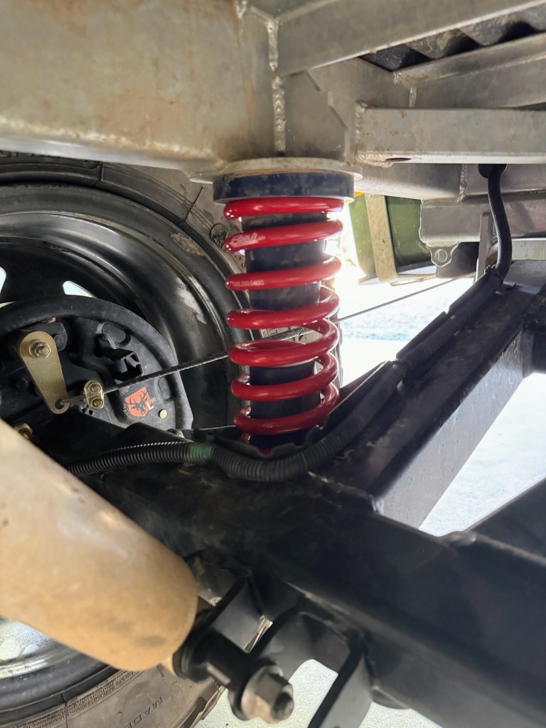
Following fitting of the 400lb per inch springs, the spring deflection at rest has increased by only 10mm, so the ride height is 10mm lower, and this suggests the calculation was correct.
Eibach Coil-over Springs
As Kings no longer produces the KPS range, I needed to find an equivalent 10” stack and 2.5” internal diameter spring set. It turns out that Eibach produces an appropriate 400lbs per inch spring, as well as many other spring rates, in the correct sizing.
I used Ian Boettcher Race Parts, in Queensland, to supply the parts, and they delivered the correct Eibach Springs very quickly.
Fitting the Coil-over Springs
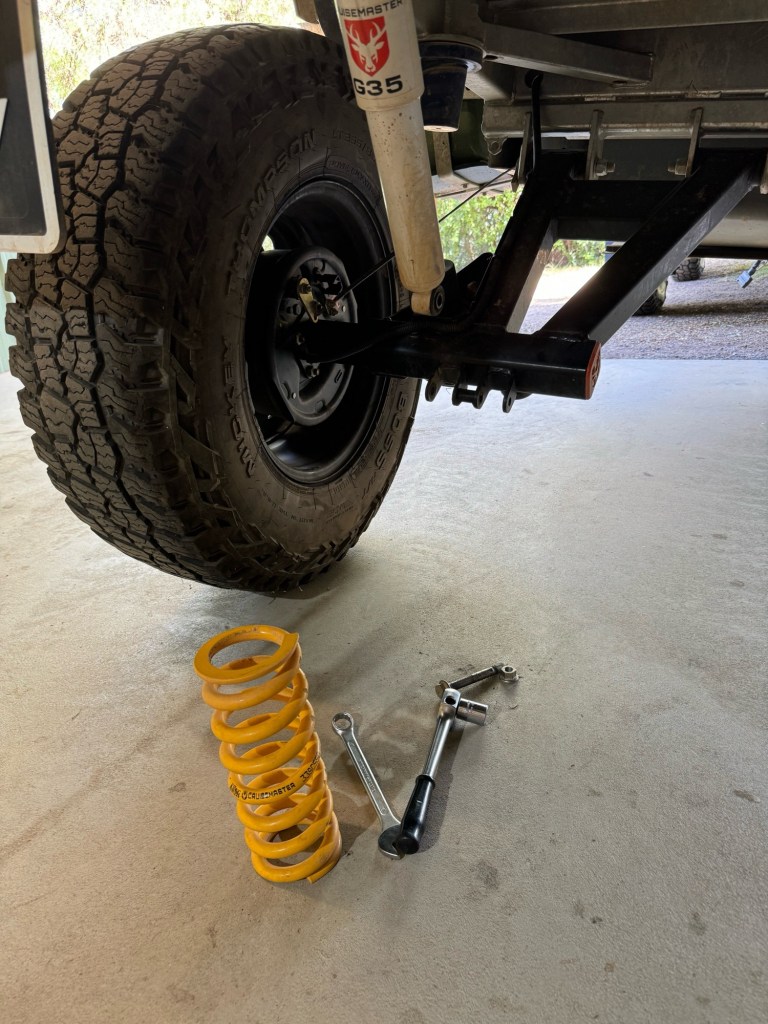
To fit the replacement springs into the XT Freestyle suspension system the lower bolt from the damper needs to be removed, and then, if the Pod frame is raised, the swing arm will droop to allow the spring to be easily exchanged.
There is no need to remove the trailer wheels, provided that the trailer body can be lifted high enough to allow the trailing arm to fall open sufficiently for the spring to be removed.
Refitting is the reverse of removal, but some thread locker should be applied to the damper bolt retaining nuts.
Conclusion
Fitting lower rated springs to the XT Freestyle suspension in a Stockman Pod Extreme tunes the spring rate to the lower actual working mass of the very light Pod Extreme.
As Cruisemaster doesn’t provide this option, but does use standardised coil-over spring sizes in the XT Freestyle suspension, it is relatively straight forward to do your own calculation, and get your springs properly tuned to the actual trailer GVM.
Historical Update
Resulting from this blog, I have heard on good authority that in the past Stockman used to use softer springs in their Extreme Pods. But many prospective customers demanded higher load capacities (to the detriment of ride quality) from their Pods, and Cruisemaster ceased to offer lower load rated suspension systems (at a guess, possibly related to King Springs closing production of their coil-over KPS range). So as a result all the production Pod Extremes are now delivered with a 1250kg GVM rating.
In November 2022 Eaton launched their Truetrac differential for the Jeep Wrangler JL and Gladiator JT. This provides a new option to increase the on-road (and off-road) traction performance of current generation Wrangler and Gladiator vehicles.
So here I’ll discuss the various cross-axle differential systems, their general characteristics, and their relevance to use in the Jeep JL and JT vehicles, and my specific experiences in installing an Eaton Truetrac in a Wrangler JL Rubicon.
In my opinion, the factory installed standard solution, using a selectable lockable open rear cross-axle differential, is not the right solution for the most driving situations. But rather the rear “locker” is only the best option for some extreme off-road rocky terrain situations that occur very infrequently (except in the minds of the Jeep marketing department).
This discussion suggests that in almost all traction situations a Torsen cross-axle rear differential will outperform a selectable “locker” open differential, and further will optimise the traction performance of the vehicle mated with the Jeep BLD system.
Differential Types and Mechanics
About 5000 years ago in Mesopotamia the first wheeled Chariots appeared. These early wheeled vehicles used freely rotating wheels attached to the end of a fixed (non-driven) axle, and that remained the case throughout the era of horse power.
Fixed axle – rotating wheel.
It was only with the invention of the steam-engine and locomotion in the 1820’s that the axle needed to drive the wheels, and be driven by motor power, and later in automobile applications there was a need to allow the speed of the driven wheels to vary relative to each other, and the cross-axle differential gear was invented and patented in 1827 by Onésiphore Pecqueur.
Open Differential
The cross-axle open differential allows the speed of the two half-axles to vary from 0% to 100%, and it delivers constant torque split to each half-axle. The ratio of the torque split is set by the size of the side gears relative the pinion gears. Usually (always) in automotive cross-axle applications the side gears are equally sized and this splits the torque exactly half to each half-axle, i.e a 50:50 split of torque. Interestingly, the first use of an automotive cross-axle differential was by an Australian in 1897 in his steam powered car.
It is worthwhile to introduce Newton’sThird Law in terms of torque delivered to an object (half-axle or drive shaft): for every action (torque) there is an equal and opposite reaction (torque). The statement means that in every interaction, there is a pair of torque forces acting on the two interacting objects. The size of the torque on the first object equals the size of the torque on the second object. The direction of the torque on the first object is opposite to the direction of the torque on the second object.
This means that although we often talk about the engine torque delivered through the drive shaft when speaking about a cross-axle differential, what we’re really interested in is the reaction torque generated by friction or traction from the ground to the tire (wheel) attached to the end of the driven half-axle. It must be understood that the engine torque delivered to a half-axle will always equal the reaction torque generated by the tire (wheel) on that half-axle. If the tire (wheel) has no traction it cannot provide a reactive torque, then the engine will not deliver torque to that half-axle.
Over time the shortcomings of the open differential became obvious when different road surfaces supported unequal wheel torque, such as when one wheel is on ice, mud, or is not in contact with the road at all. In an open differential the maximum torque delivered by the engine will be twice the minimum torque reaction from one of the wheels, ignoring friction from the vehicle driveline. Therefore if one wheel is on ice supporting almost no torque reaction, then the engine will only be able to deliver torque as if both wheels were on ice. If one wheel is in the air, then similarly the engine will deliver torque as if both wheels are in the air (i.e. no torque at all).
Limited Slip Differential
In the 1960s high power USA “Muscle Cars” started to use limited-slip differentials to prevent the “one tire fire” as their available engine torque would be more than twice the minimum wheel reactive torque which would cause the weakest (lowest friction) tire to break traction reducing its reactive torque capability to almost zero, and as a result the overall torque delivered by the engine would drop to almost zero and the car would sit “smoking” a single wheel. The limited slip differential helped to overcome this problem by using clutch packs or springs to set the minimum torque delivered to each wheel. This means that the torque delivered to each wheel is not able to go to zero, but is set to a minimum value determined by the clutch spring design, however the torque split remains exactly 50:50 as in an open differential.
The limited-slip differential goes a long way to solving the issues encountered by high powered vehicles both on-road and off-road, but it does introduce an additional maintenance as clutch packs in the differential need to be maintained, and they will wear out often if used aggressively.
Locking Differential
For off-road and some extreme on-road applications locking differentials have become very popular. When activated, locking differentials effectively return the axle to a solid locomotive beam axle, and this inverts the torque and speed relationship of the open differential by holding the wheel speed relationship to be constant equal to 1:1 but allowing the torque reaction from each wheel to vary from 0% to 100% depending on what is available. Therefore if a wheel is in the air, it will produce 0% reactive torque forcing 100% reactive torque to be produced by the other wheel, but both wheels will rotate at exactly the same speed. Using a locked differential or “spool” is only useful in extreme situations, and the lock cannot be left permanently engaged. A locked or solid axle will make it very difficult to turn the vehicle, as it will want to travel in a straight line with both inside and outside wheels rotating at the same speed, so it cannot be used in most situations. To overcome the drivability limitations the spool or solid locomotive axle produces both automatic and selectable locking differentials have been produced.
Automatic locking differentials such as the “Detroit Locker”, or the “lunchbox locker”, are constructed with each wheel connected to the drive shaft via a freewheel gear which, when the vehicle is moving in a straight line, will allow the torque to to each wheel to vary from 0% to 100% as in a solid single axle, but when cornering will allow a faster moving (outside) wheel to over-rotate freely, while providing torque to the slowest moving (inside) wheel. The main disadvantage of this solution is that, when travelling around a corner, drive torque is only available to the inside (slow) wheel while the outside (fast) wheel is freewheeling, but as the inside wheel is the most lightly loaded in cornering it is usually least capable of providing reactive torque. Also drive to the inside wheel produces poor vehicle dynamics, tending to kick the rear of the vehicle out, and this is used extensively in drifting where going sideways is a good thing.
Selectable locking differentials, such as the Jeep eLockers fitted to the Wrangler JL Rubicon, allow the driver to choose whether the differential is in open mode (the usual case) or set to locked mode when needed. The driver is forced to select between the two extremes, either locked torque and open speed (the open differential) or locked speed and open torque (the locked differential), depending on what might best suit the expected traction situation.
And the answer is: it depends. Essentially, the driver is trying to guess the vehicle traction dynamics, which usually change rapidly. Usually in technical off-road driving the driver will first attempt an obstacle with an open differential, and only when they have failed the obstacle will they will engage the differential lock and try again. Very much a trial and error solution.
Whilst it is possible for the driver to actively select either open or locked differentials in low speed technical off-road situations, it is not practical for the driver to undertake this decision every time they face a different real world low traction or differentiated traction situation. In every day situations of low traction, such as accelerating from a country dirt roadside (one wheel on dirt, one wheel on tar), or crossing a curb, or snow or slush on the roadside, sand and rock, ice patches, or any other impossible to predict situation it is certain that the vehicle will be running with an open differential and will therefore face the limits of unbalanced wheel traction.
Torque Sensing Differential (TORSEN)
Ideally the vehicle cross-axle differential would immediately sense which wheel can provide the greatest reaction torque and adjust (or bias) itself to deliver the available engine torque to that wheel without any conscious input from the driver.
In 1958 Vernon Gleasman patented the torque sensing or Torsen differential, which uses the gear separation forces and friction generated by the sun planet worm gear to provide cross-axle torque biasing. The Torsen differential works because when input torque is applied to a helical gear, it creates a series of thrust forces that push that gearing into the differential casing. When these forces push against the wall of the differential casing, that contact creates friction. As the torque load increases so do the forces and so friction increases in proportion to the amount of torque applied. That gives the Torsen differential the ability to support a lot of reactive torque (traction) imbalance when under heavy throttle conditions, yet it still can differentiate freely and smoothly at low engine torque levels, so the car is docile and easy to drive and manoeuvre.
The Torque Bias Ratio (TBR) is a measure of how strongly the Torsen differential will lock. The higher the TBR setting, the more aggressive the traction performance locking. The TBR represents the ratio of high traction to low traction that the Torsen differential can allow while remaining locked. Typical TBRs in production Torsen differentials ranges from 3.5:1 in the Eaton Truetrac, to 2:1 to 6:1 in the Quaife ATB depending on the specific application for front or rear cross-axle.
To extend the TBR concept to other differentials it can be seen that the open differential or a clutch based limited slip differential provides a TBR of 1:1, as the torque split is fixed 50:50 by design. A locked or spool differential has an infinite TBR, as the ratio between the two axles’ torque can be up to 100:0, where one wheel can possibly deliver 100% but the other delivers 0% torque,.
It is worth noting that the HMMVW, perhaps the most iconic modern off-road vehicle, uses two cross-axle Torsen differentials. Although the Torsen differentials provide the best traction for the military cross country application, the fact that the military KISS principle applies and there is no operator input required (unlike a selectable locking differential) and no additional maintenance procedures are needed (unlike a clutch based limited-slip differential) probably also contributed to the US military’s decision to use Torsen differentials in the HMMVW.
Brake Locked Differential
The Jeep JL/JT range are equipped with an Electronic Stability Control system which consists of Stability Control, Traction Control, and Brake Locked Differentials. These electronic assistance systems are independent of the type of mechanical cross-axle differentials installed.
Usually for extreme off-road usage in 4WD Low Range the Stability Control and Traction Control systems will be disabled, but the Jeep Brake Locked Differential system cannot be disabled.
The purpose of BLD is to simulate true locking differentials, described above, in order to provide additional torque to the wheels with traction. A Jeep JL/JT equipped with BLD will be able to successfully navigate many obstacles similarly to a vehicle with true locking differentials.
The Jeep JL/JT has speed sensors on each wheel and therefore it is able to know when one wheel is spinning faster than the wheel on the opposite half-axle. When it senses one wheel spinning and the other not, it automatically applies the brake force to the spinning wheel using the ABS system. As in an open differential the torque is split 50:50 and now that the braked wheel is providing reactive torque, then so is the wheel with traction. In many cases the extra torque is enough to keep or get the vehicle moving.
The BLD feature does not care how fast the wheels are turning, nor does it try to limit how fast they’re turning, so long as they are turning at the same speed.
The JL/JT Rubicon Off-road+ mode further accentuates the standard BLD capability by intervening much more quickly and aggressively when a wheel speed differential is detected.
When a vehicle is equipped with a Torsen differential the BLD system will function normally but it will be much more effective as the brake reaction torque from the braked (spinning) wheel will be multiplied by the TBR, 3.5:1 in the case of the Eaton Truetrac, providing 3.5 times more available drive torque to the other wheel than from an open differential from the same BLD brake force application.
Installation for Wrangler JL Rubicon
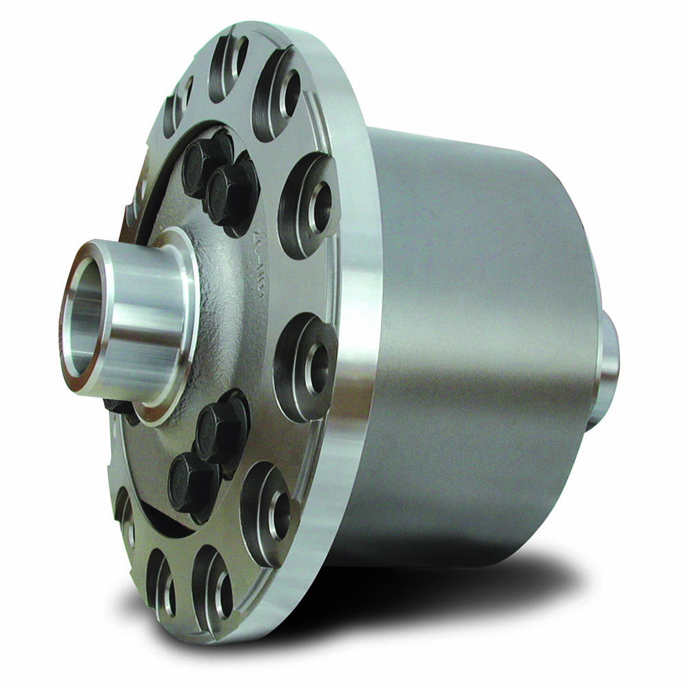
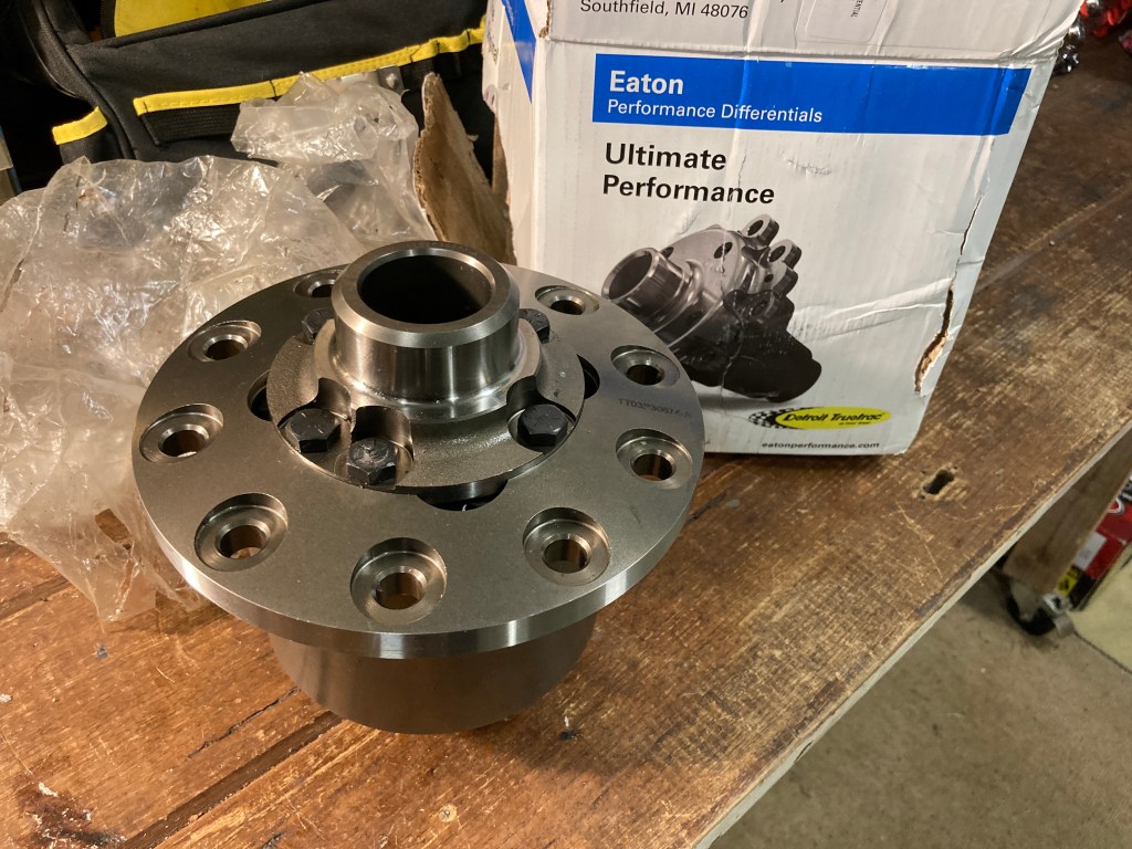
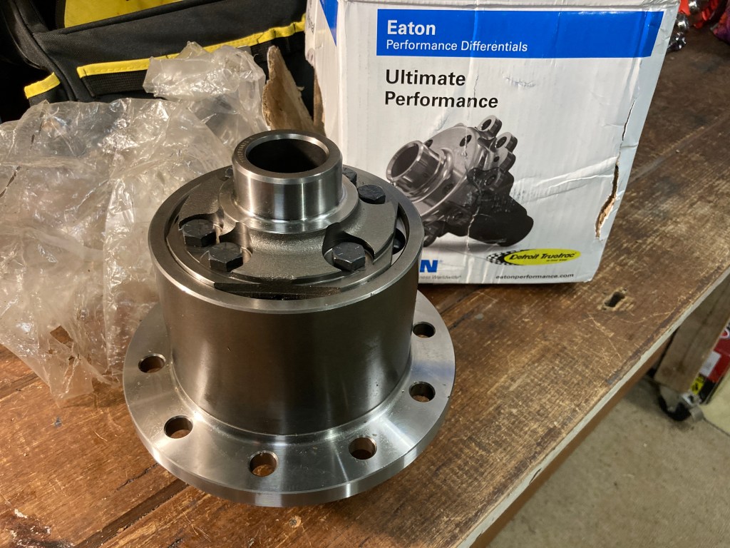
The new Eaton Truetrac 917A736 for the Wrangler JL and Gladiator JT is specified for all Dana 44 M210 and M220 axles, being for both front and rear cross-axle differentials. The JL/JT Truetrac is a 4 pinion implementation, the strongest that Eaton produces. This joins the existing availability of the Nitro Helix Torsen differential also available for the Wrangler JL or Gladiator JT.
For reference, the Eaton Truetrac 917A736 is available in Australia from Harrop Engineering, though I used Summit Racing in the USA to obtain my example.
Eaton provides a master installation kit K-D44-220 for the Jeep JL/JT rear axle application. This installation kit should be obtained with the Truetrac differential, as the carrier bearings are only available from Jeep, and are exorbitantly expensive.
It must be noted that the Eaton 917A736 is not specified to be compatible with the JL/JT Rubicon trim level. This is because the Rubicon is already fitted with an electrically selectable Jeep eLocker, and the Rubicon rear axle lengths are different to the standard axles.
To fit the wider differential centre in the Truetrac differential, one standard length Wrangler JL/JT rear axle (32.3″) is required for the right hand side, as the Rubicon right hand rear axle is 33.9″ and is too long and will not fit. It is best to buy this axle in preparation. As I had not purchased the correct axle in advance a Crown JK Rubicon RH axle was used.
For other Wrangler JL or Gladiator JT trim levels such as Sport, Sahara, Night Eagle, or Overland, it should be quite straightforward to install the Eaton Truetrac TORSEN differential.
Z Locker OEM
As the Rubicon drivetrain management system is set to support both front and rear Jeep selectable eLockers, by removing the existing rear differential and sensors the drivetrain management system would believe that there is a system fault, and would generate system errors preventing both eLockers from being engaged.
However there is a product from Z Automotive called Z Locker OEM to resolve this issue. This part is designed to spoof or fool the Rubicon drivetrain management electronics to overcome the fault inherent in the Rubicon selectable locking differential whereby when a locking actuator sensor fails it causes the vehicle electronics to believe that the locker is inactive and therefore register a system fault, preventing the use of both front and rear differential lockers.
The Z Locker OEM can be installed to the Rubicon rear eLocker wiring, but not connected to the rear differential housing, and the entire axle wiring loom is then zip-tied up out of the way under the vehicle body. The Rubicon electronics believes the rear selectable locker is functioning normally, which also allows the front selectable locker to function normally and the rear selectable locker to be replaced with the Eaton Truetrac differential.
Overall 4WD System
Note that this discussion is relevant to the Jeep JL/JT rear cross-axle differential only. Whilst Torsen differentials can be used very successfully with high power front wheel drive vehicles and in the front axle of 4WD vehicles, in the specific case of the Jeep JL/JT Rubicon with an existing selectable locking open differential it is sensible (cost effective) retain that capability in the front axle. Other Jeep JL/JT trim levels should use either a Torsen front cross-axle differential, similar to the HMMWV but combined with the Jeep BLD system, or to use a selectable locking differential, similar to the Rubicon eLocker.
When used in 4WD Part Time mode the Wrangler 4WD system uses a locked clutch centre transfer case which will allow 0% to 100% torque split between front and rear cross-axles, and using the selectable locked front cross-axle differential from 0% up to 100% of the available engine torque can be directed to either of the front wheels. This allows the entire engine torque to be delivered through one front wheel, should it be able to provide sufficient traction. Several real world testssuggest that if one cross-axle can be locked, then it should be the front axle.
As the Torsen cross-axle differential responds instantly to changes in cross-axle dynamic traction, it continually optimises the torque balance between the left and right wheels. Any tire slippage is sensed within a few degrees of rotation (based on internal gear lash which is no more than 1 or 2 degrees), and torque is biased to the other axle and tire. If the slipping tire cannot support any traction and starts spinning freely then the Jeep BLD system will intervene and its effectiveness will be enhanced (multiplied) by the Torsen TBR further improving the outcome.
By using a Torsen cross-axle differential in the rear axle we’re optimising traction in 2WD, 4WD high range, and 4WD low range, on all differentiated friction on-road and off-road surfaces, whilst adhering to the KISS Principle. So we’re generating the best available traction for most surfaces, all of the time, with no need for operator intervention. And, by retaining the front cross-axle lockable open differential, we have a traction solution for any remaining extreme 4WD low range situations (with one wheel on each axle off the ground, for example).
Testing Results
Check back late July 2023 for more extreme testing, but initial experience backs the discussion above. Acceleration in 2WD is balanced and smooth from soft muddy verge to sealed road. Muddy tracks are no problem in 2WD. So far in a very wet and muddy June/July, there’s been the expected good result.
On Rocky Track, Toolangi State Forest, there was no problem with rocky terrain. Performance was similar to other JL/JT vehicles on the trip. There was no need to reach for the locking front differential.
On sand the results are very good. Big Dune, in the Big Desert State Forest, usually poses a serious challenge for most vehicles but here was easy and controllable.
Big Dune, Big Desert State Forest
Driving in the Flinders Ranges (Echo Camp Backtrack, Mt Buggery Gorge, Mt Samuel, Skytrek) means shale and loose rock surfaces. It is noticeable that large pieces of loose rock are not thrown out by the rear wheels, but rather when a loose unstable rock under a wheel begins to slip torque is biased to the other wheel and nothing is thrown out. This is in contrast to other open differential vehicles I was following on the tracks, which would often be seen digging holes in the track’s climbs and they would also throw rocks out the back of their vehicles.
Playing in 2WD on sand, shows two rooster tails with the largest from the more loaded outside wheel.
More on upgrading the Wrangler JL in the Build Log.
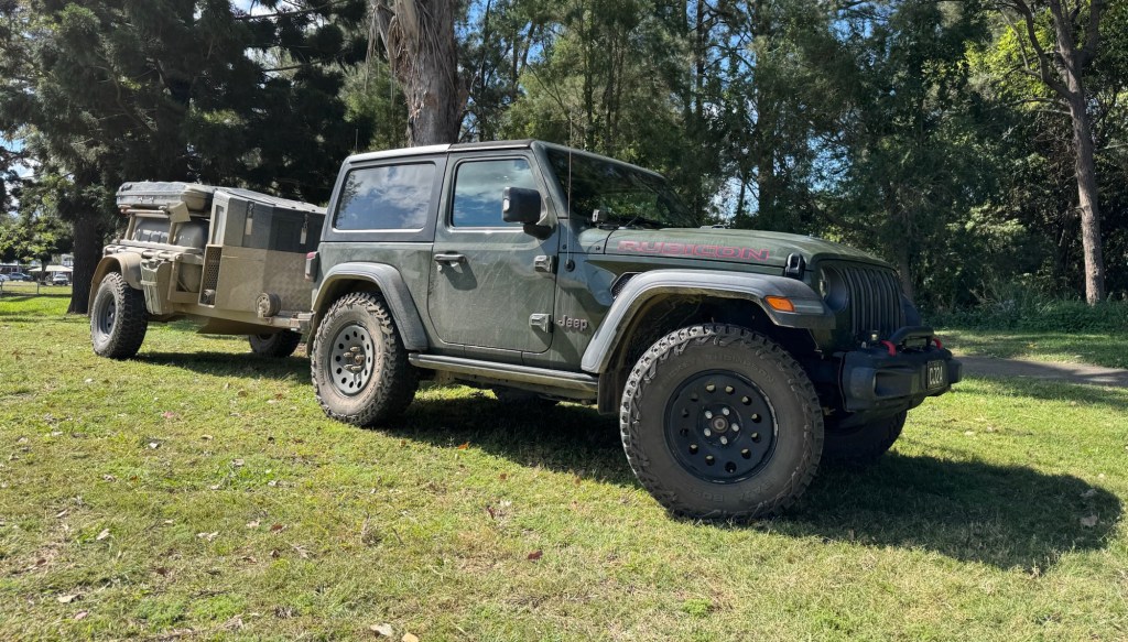
In Curb Weight I’ve spoken about dividing the weight between the vehicle and an extreme off-road trailer, and how the vehicle was modified to be able to pull the trailer successfully. In this post I’ll cover how I’ve divided the types of load between the vehicle and trailer, and how I’ve built an equipment rack to support the load being carried by the vehicle.
I must mention that a key requirement for the vehicle build was that any overlanding related modifications had to be entirely reversible, and removable. The rear seat needed to be able to be refitted so that the 2 door Rubicon could carry 4 people if needed. So my equipment rack must easily removable too.
Vehicle Contents
I would like the vehicle to be able to leave the trailer at a “base camp” and still have the required equipment to sustain a day (or in an emergency several days) away from the camp site. This dictates what I need to build into the vehicle, and what I can leave in the trailer.
The vehicle must therefore contain the following items.
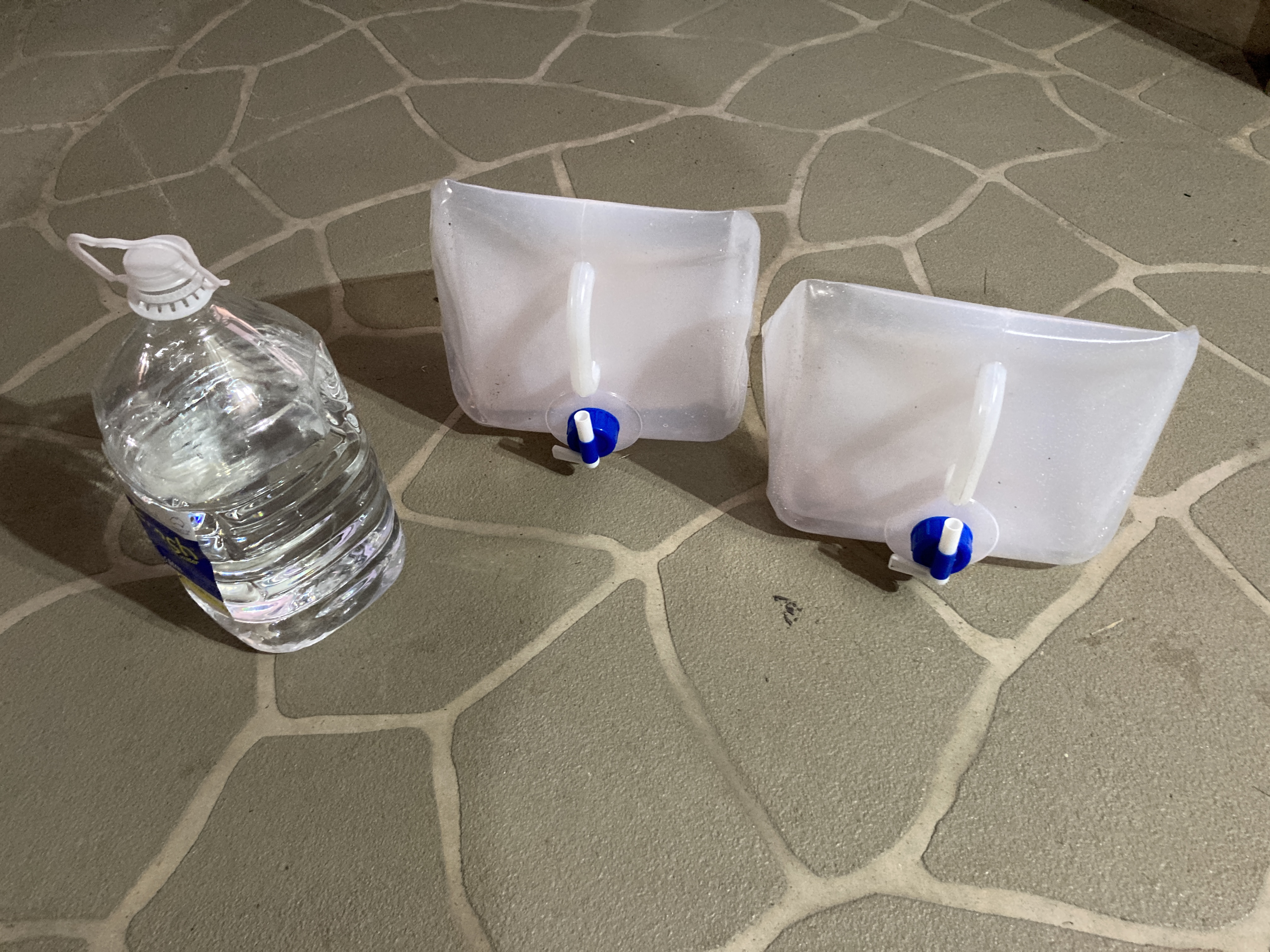
Drinking Water – Potable water either 20 litres or 40 litres depending on the requirements.
Refrigeration – A 40 litre refrigerator, sufficient to hold frozen or cooled items depending on the length of the passage.
Power – 12V and 240V AC systems to power the refrigerator, cooking, communications, and tools.
Food Preparation – using 240V AC induction cooking, kettle, and coffee machine.
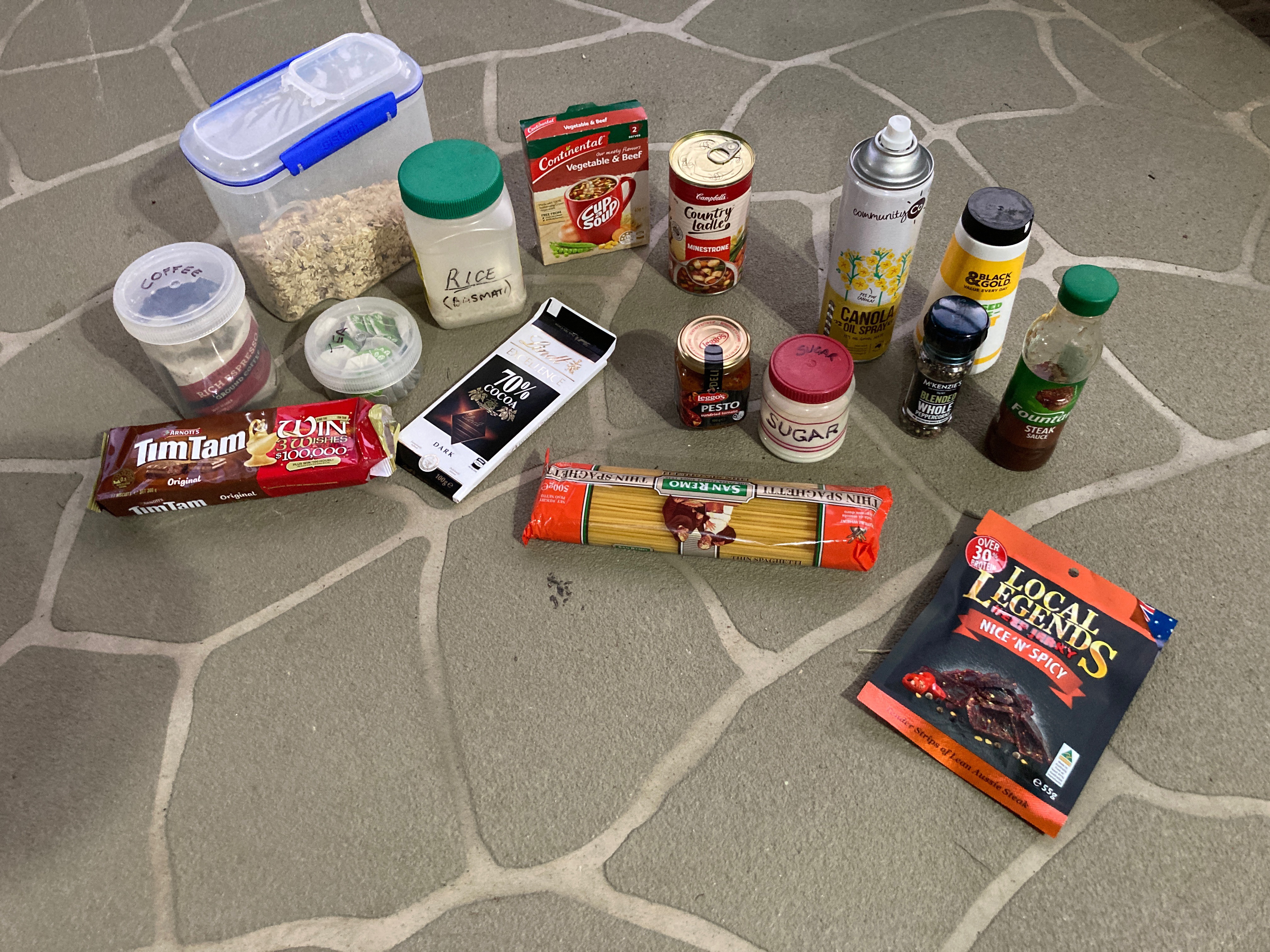
Food – Chilled and dry food sufficient to cover the entire passage.
Clothing – Warm clothing, sufficient to overnight should needs dictate.
Communications, and Electronics – Both UHF and satellite communications system for regular and emergency use.
Based on the item lists I’ve prepared the weight of this equipment and stores should be approximately 260kg (including trailer ball weight), and this can be easily carried by the Wrangler JL 2 Door.
Trailer Contents
The Stockman Pod Extreme trailer has a number of well separated spaces, including two drawers and a large tool box, which allow it to safely store lots of smaller items in boxes without too much movement.
The trailer will carry the things that don’t need to go in the vehicle, and either too heavy or too bulky to consider putting in the vehicle.
Fuel – In Jerry Cans from 40 litres to 200 litres, depending on the length of the passage.
Water – At least 65 litres of possibly non-potable water, carried in the integrated water tank
Accommodations – Both a James Baraud Evasion roof top tent, and/or a Terka tent and stretcher bed, providing options for easy overnight or comfortable base camp builds. Also a 3m x 3m gazebo to provide shade and light rain protection as needed.
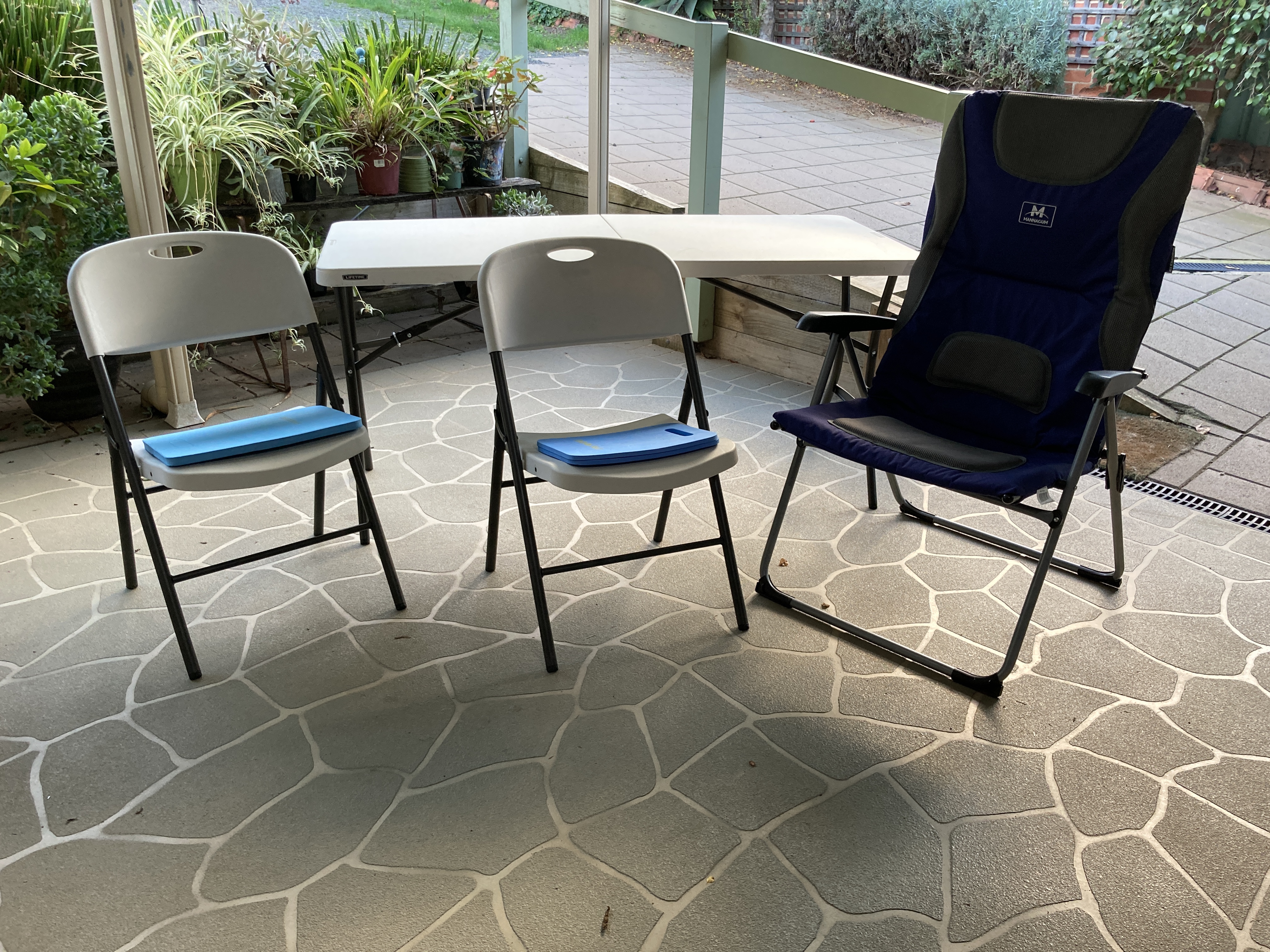
Furniture – Folding table and camp chairs.
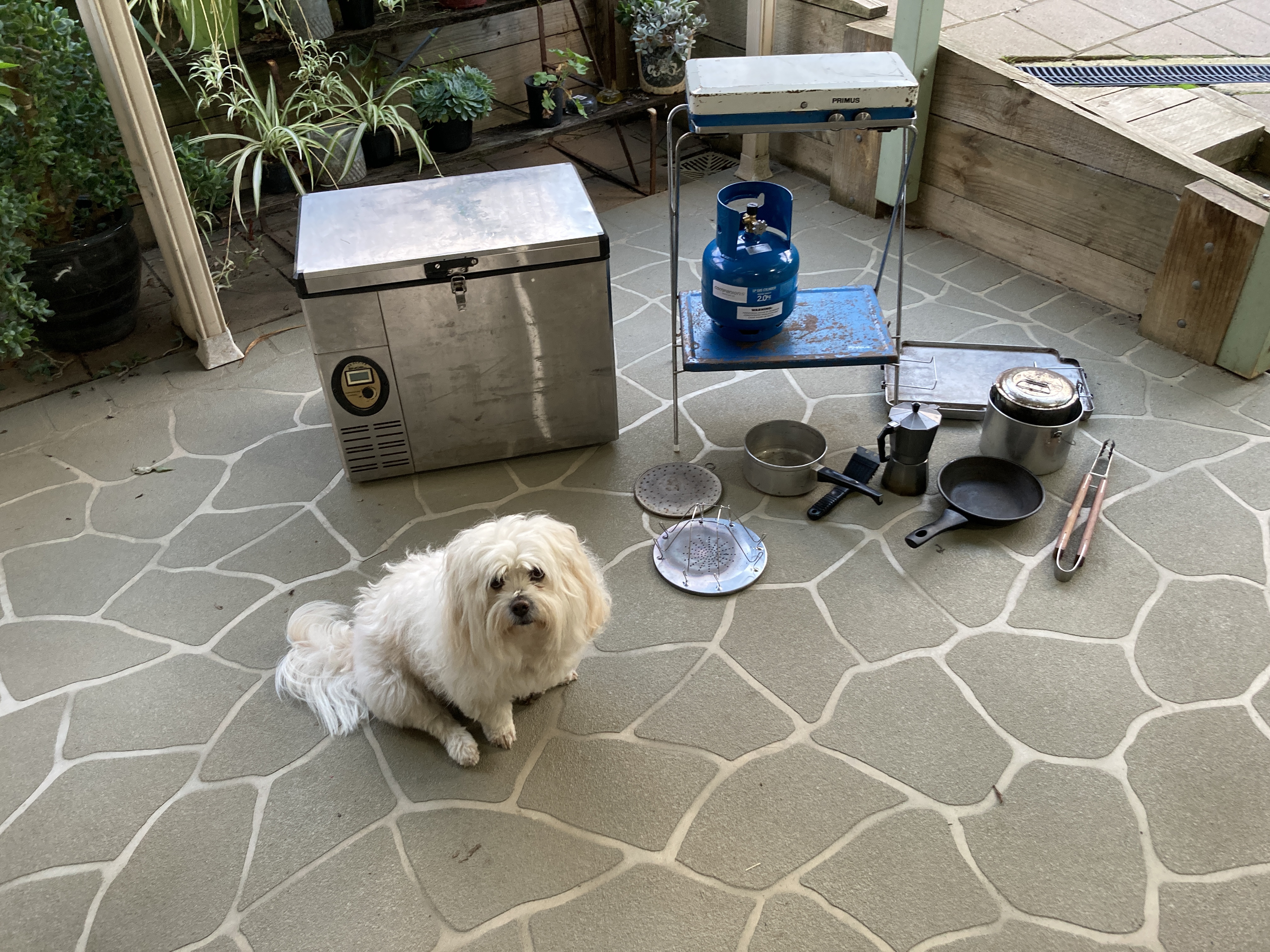
Gas Bottles and Food Preparation – Including 2 burner gas stove for food preparation.
Large Tools and spare parts – To support repair of moderately major items, and maintenance of the vehicle and trailer.
Recovery Equipment – Larger items stored on the trailer, as most recoveries will involve the trailer and necessary items can be moved into the vehicle if needed.
Toilet and Hot Water System – To provide hot water for base camp washing and showers, and toilet to provide a bit of camping comfort.
Clothing – Additional clothing and linen as required.
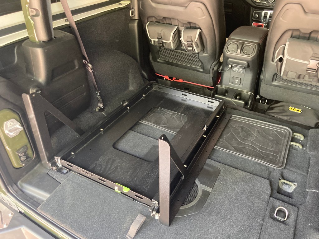
Basic Equipment Rack Design
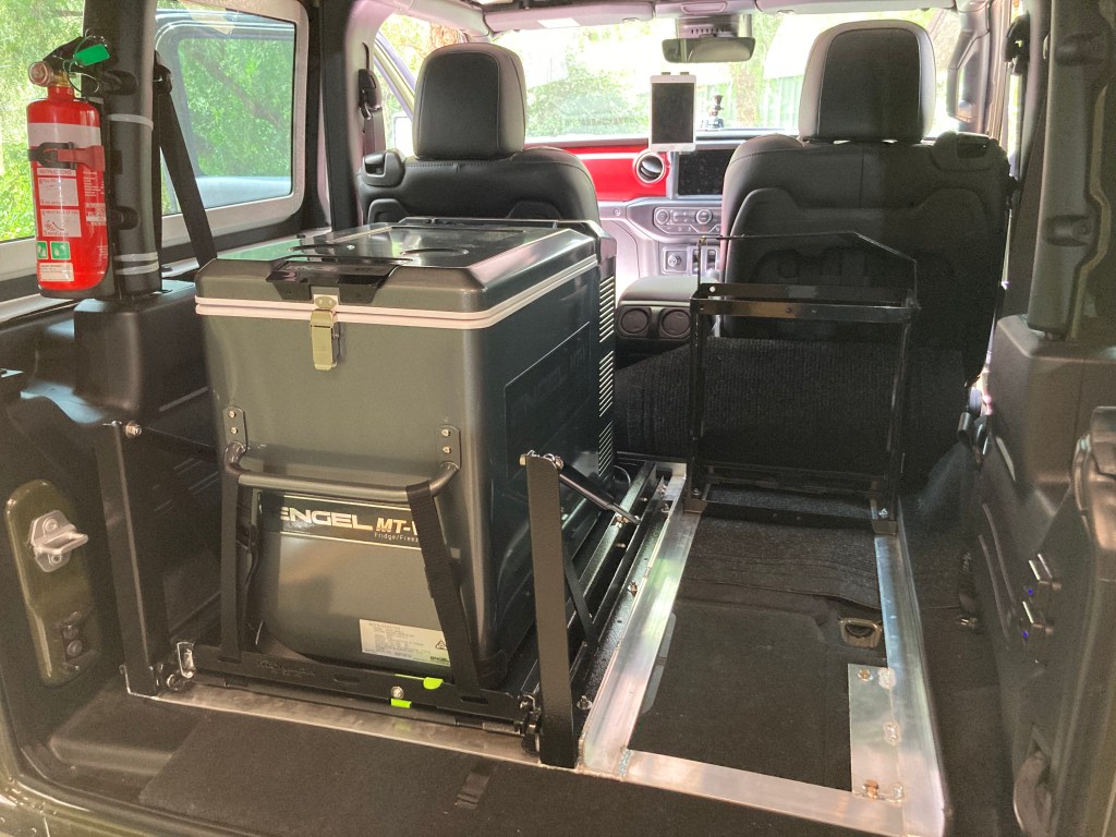
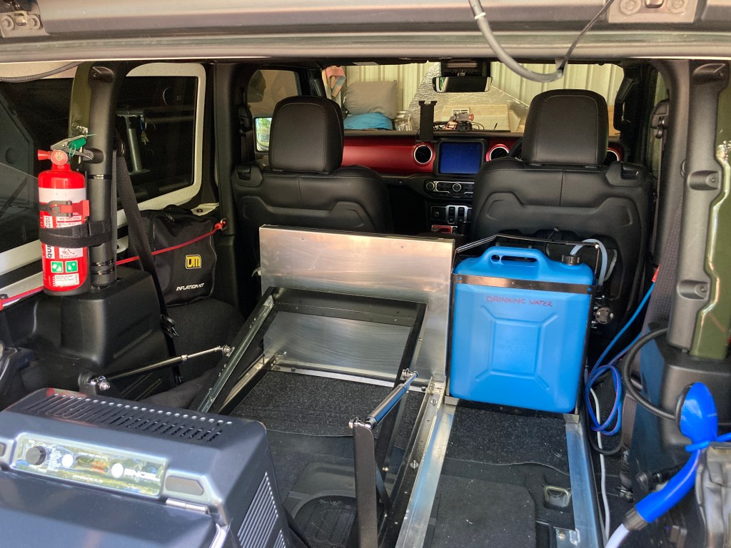
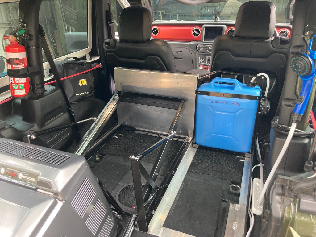
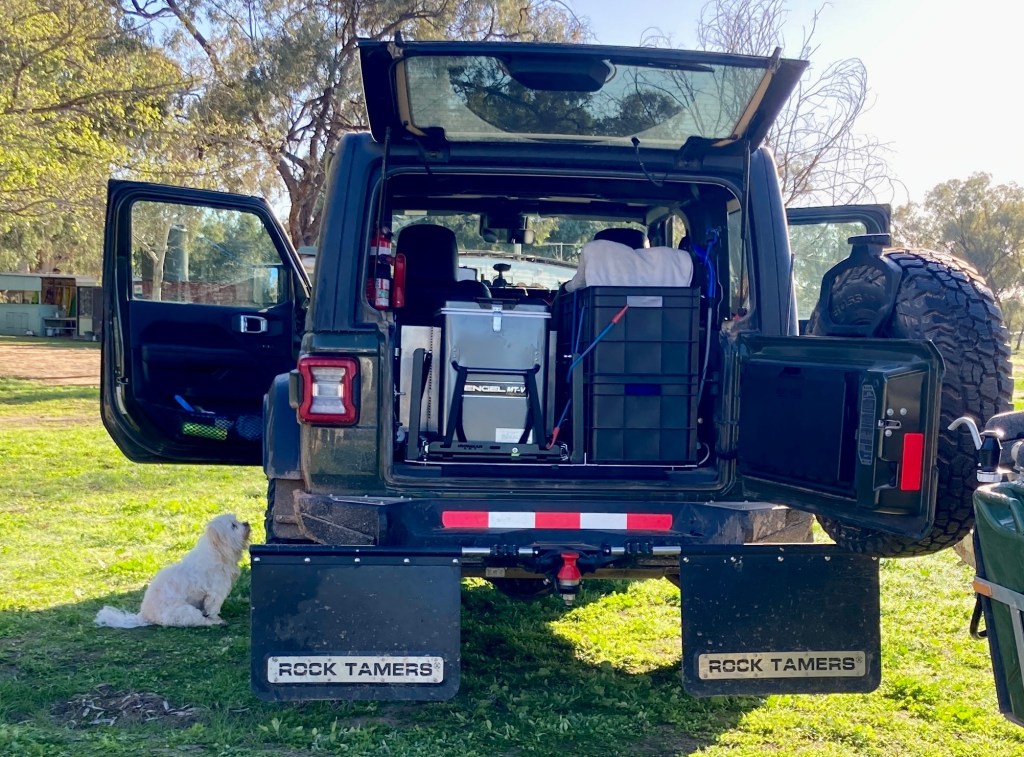
While the design has evolved over the past weeks of the build, it essentially needed to carry 1. refrigeration, 2. electrical systems, 3. water, and 4. stackable food and assorted items. All of this, in a very tight space. Since the Wrangler JL has a swinging tail-gate with a fold down tail-gate table, it made most sense to put the refrigerator on its slide on the left side and the electrical systems in front of it.
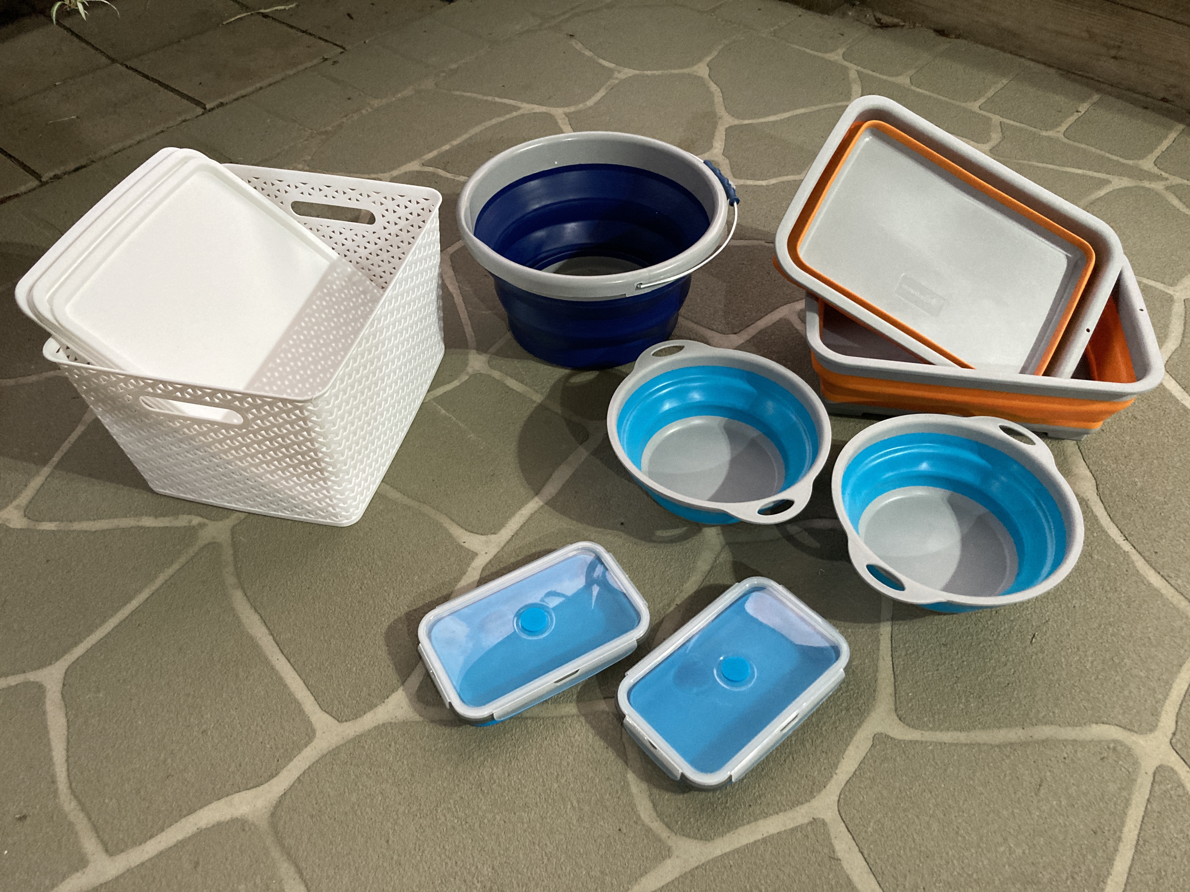
On the right side the drinking water would be stored as far forward as possible, and the food and assorted items stored in milk crates which are easily removable and stackable for access. Luckily the width of a Jerry Can is the same width as a milk crate so it was possible to use the same dimension for both.
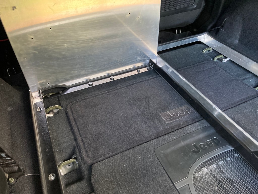
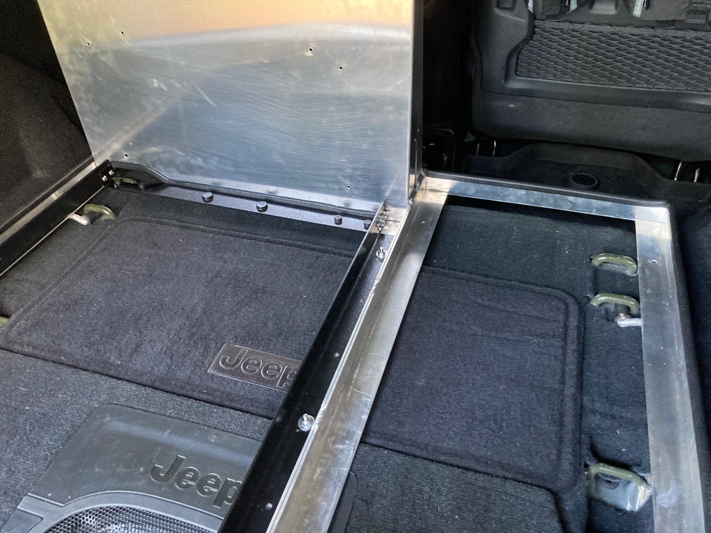
The Wrangler JL 2 Door has a number of tie down options. There are 4 integrated threaded nuts in the rear of the floor, which can be fitted with high-tensile bolts. But these rear bolt locations don’t control the front of the space effectively. Fortunately there are also strong loops in the forward floor, to mount the rear seat, which can be used to secure the load at the front.
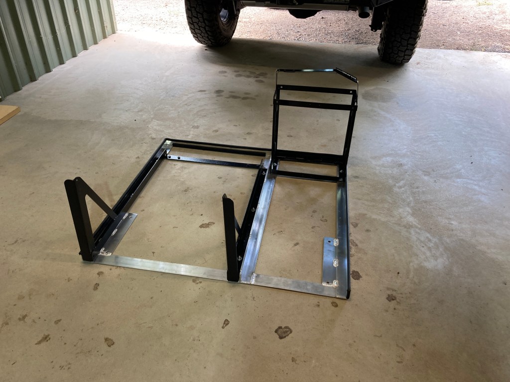
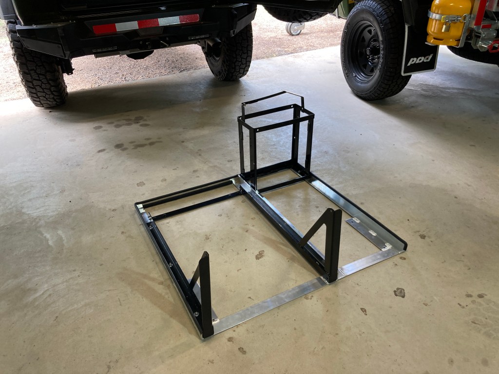
Build Process
This was a custom build, so it was sensible to build in stages so that I could change things if the equipment rack didn’t perform as anticipated. The stages below were each separated by a shake down trip, and the improvements noted through use were incorporated into the following stage.
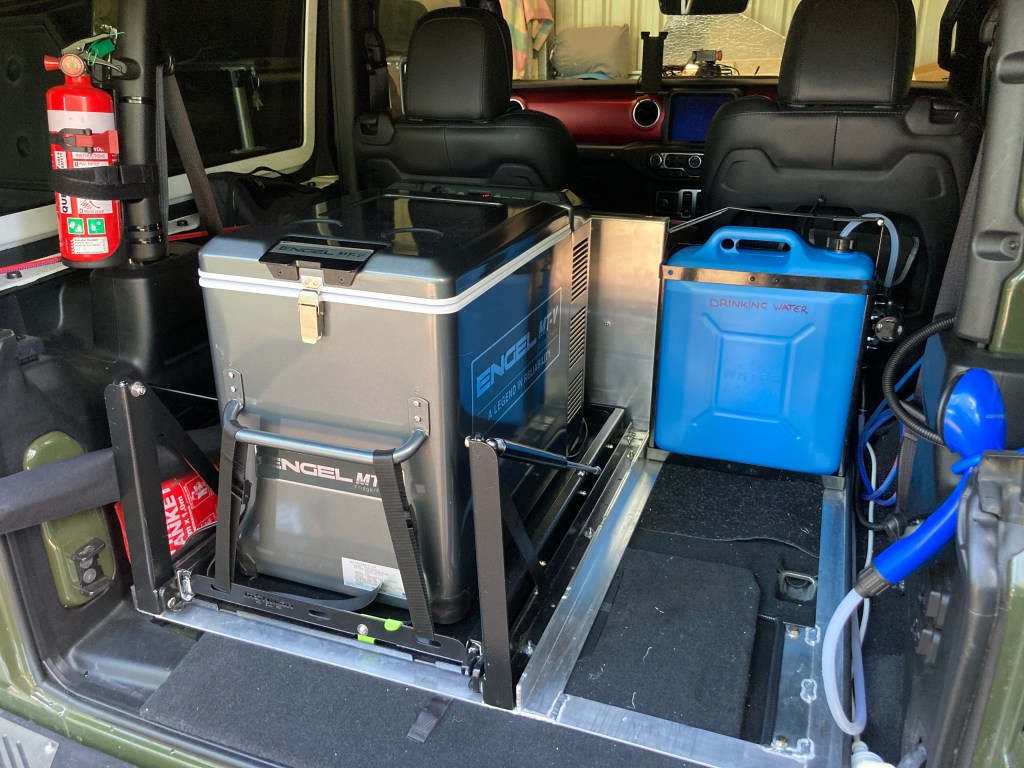
Stage 1 – Fridge Slide & Jerry Can (Water)
The first stage was securing the fridge and water in a Jerry Can. These two item could then be used to locate and tie down the other items
So this first stage worked well. I’d note that the tilting fridge slide was unnecessary, and a standard (non-tilting) slide would have been smaller, cheaper, and weigh less. I’ve also found that the tilt makes it difficult to store things in the fridge as when tilted things can’t be removed without the stacks of items in the fridge falling over.
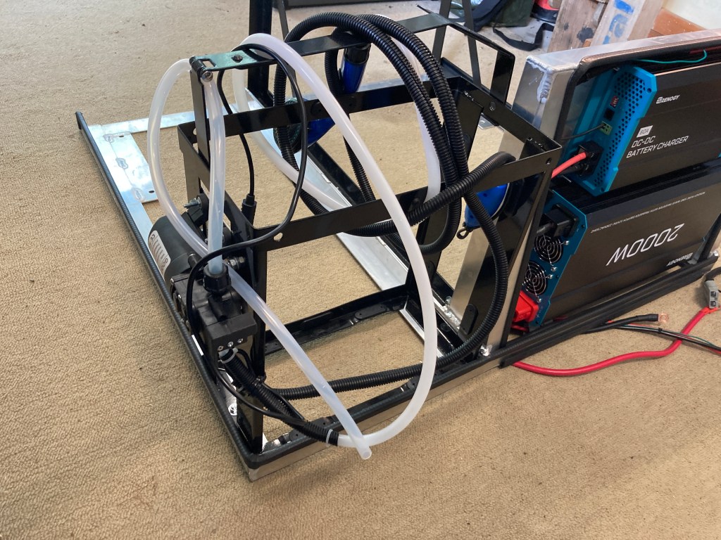
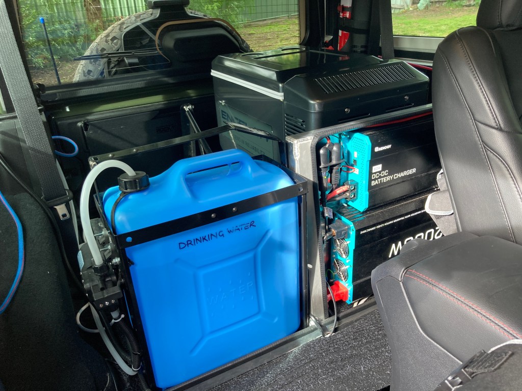
I also found that the water in the Jerry Can was unusable, as the full Can is too heavy to remove for use, so it was necessary to use a water pump to deliver the water to the food preparation area at the rear of the vehicle.
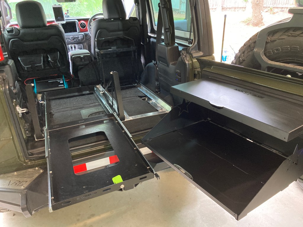
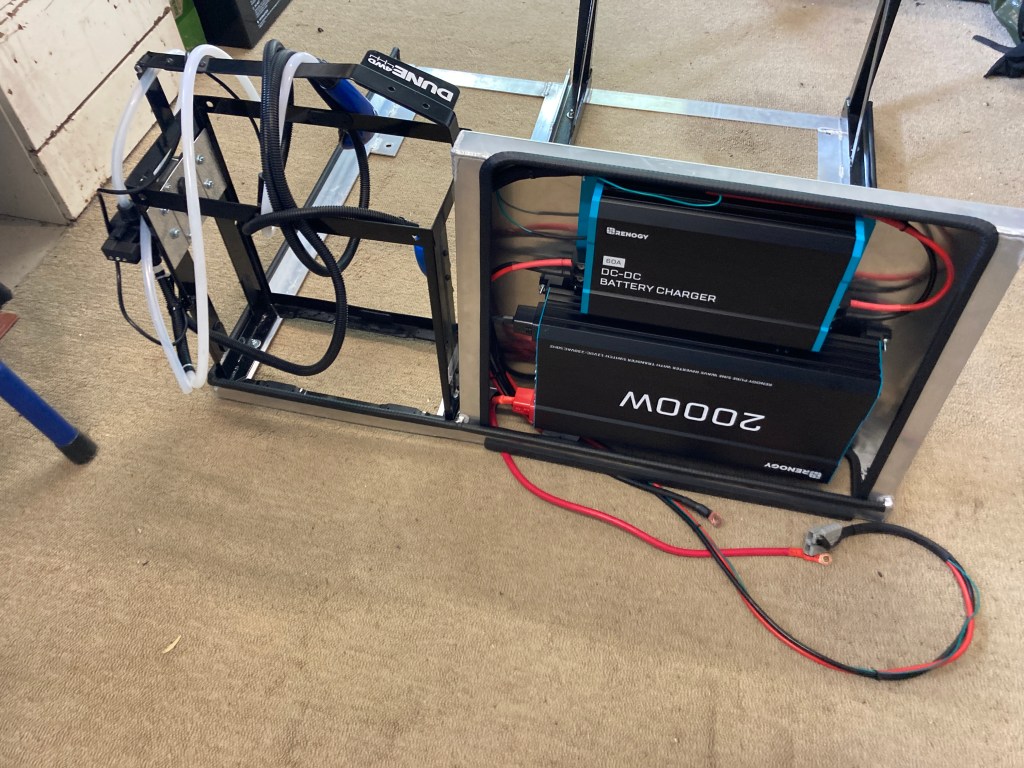
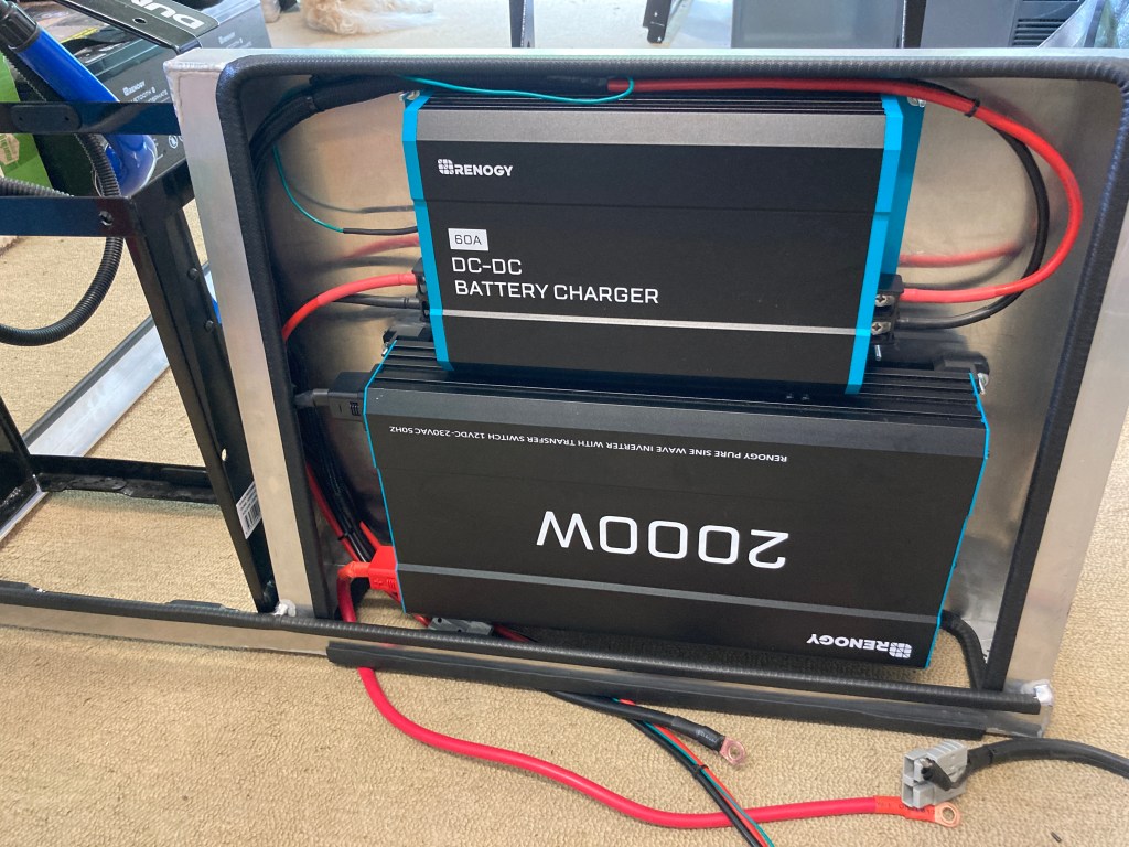
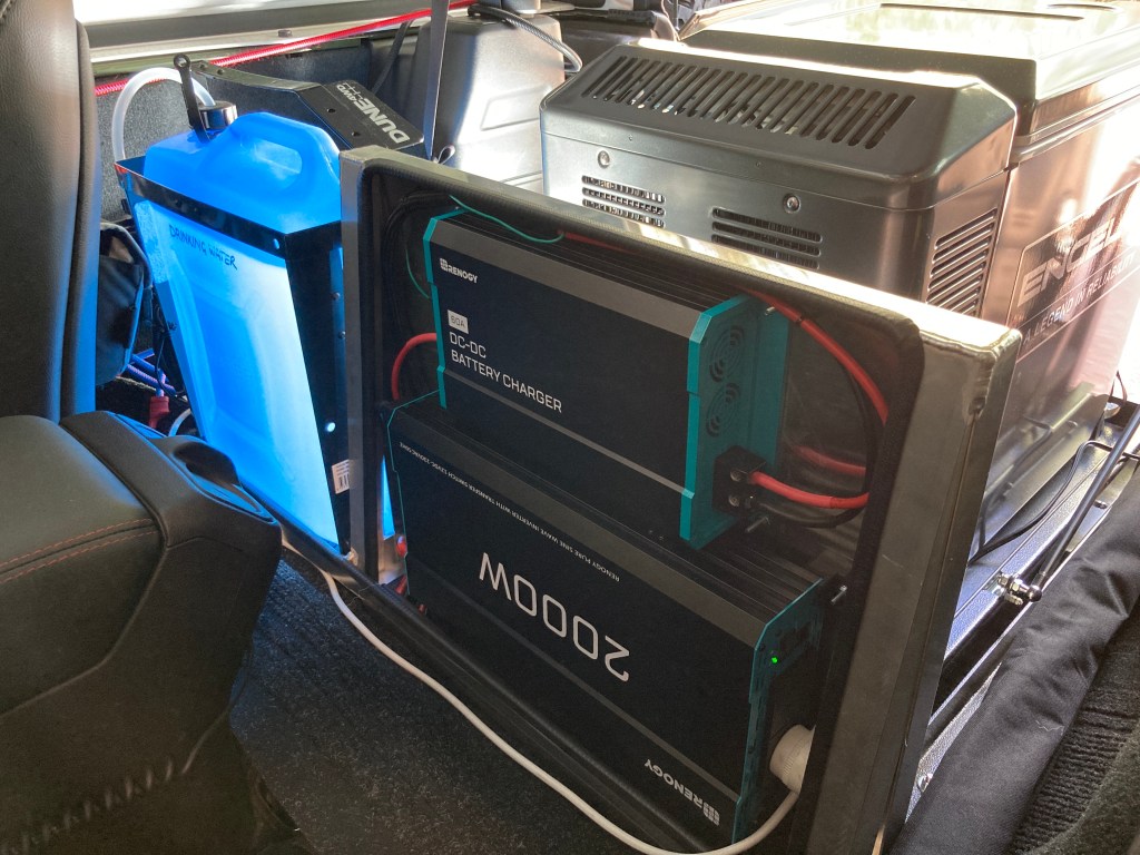
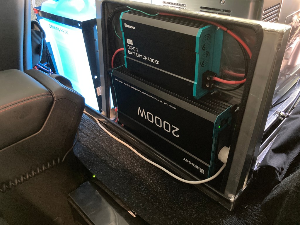
Stage 2 – Electrical Panel & Water Pump
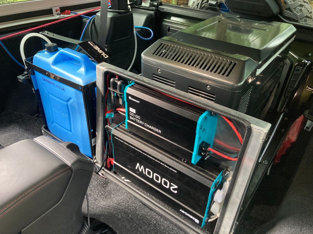
The next stage was to securely mount a Renogy 60A DC-DC charger along with a Renogy 240V 2kW inverter system into an electrical panel. The electrical panel was built onto the front of the fridge slide, and it helped to substantially strengthen and stabilise the equipment rack.
The battery charger 12V wiring is done with 6AWG cables and they do heat up during usage. The inverter 12V supply wiring is done with 0AWG cables.
Noting that the two Renogy Lithium 100Ah batteries are secured by pressing them between the front seats and the rear foot well. The end of the slide protrudes over the foot well too so the batteries are unable to move, yet they don’t require special mountings.
I attempted to use a Coleman Camp Shower to deliver the drinking water, but the submersible pump was too large to go into any available water grade Jerry Can. The answer was to cannibalise the Coleman Shower, used together with a 6 litre/min 12V pump, which works perfectly. The retention device in the cap has a hole exactly the diameter of the shower hose, so it can be inserted into the top of the Jerry Can with no leaks.
Following the second shake down all of the systems were proven to work as expected, so the final fitting and build could be completed.
Stage 3 – Final Fitting & Milk Crates
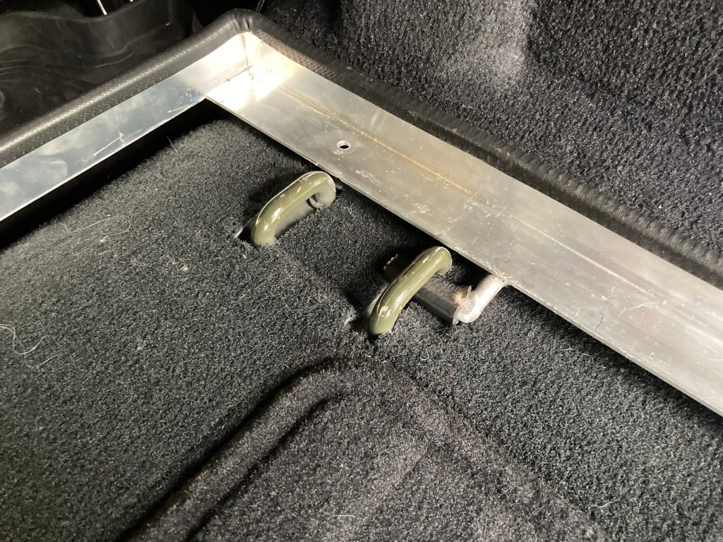
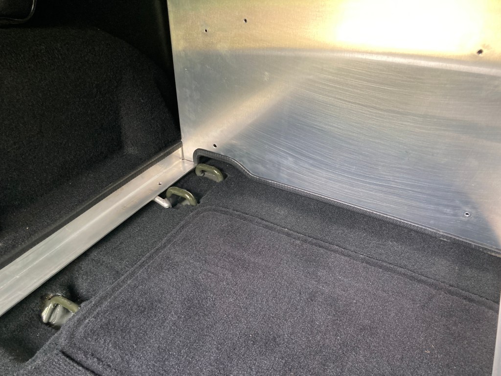
At this point the final build was to add hooks to the rack to insert into the seat loops at the front to retain the equipment rack in the event of a roll-over or other eventuality. Although the prior shake down showed that the equipment rack remains stable despite extensive horizontal and vertical shaking and even several airborne excursions.
Locating hooks under rear seat mounts.
The frame is sized to allow two milk crates to be placed one behind another, with 20 litres of water, giving a total capacity of 4 crates below the window line of the vehicle. Where 40 litres of water is required for a passage, it will be necessary to stack up 3 crates, which will affect rear visibility but otherwise this is a useful option. As a maximum up to 6 crates can be stacked and restrained in the rear of the vehicle.
Four crates.Four crates.
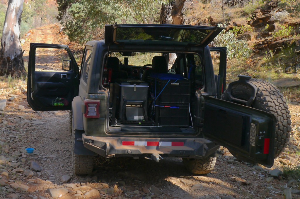
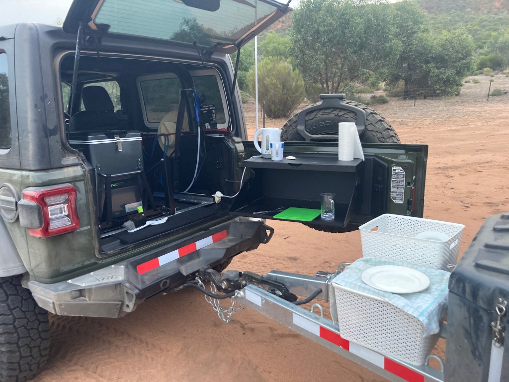
The System In Use
The initial usage in two shake down trips shows that the build has been successful. Water, power, and food are all easily reached and used to safely prepare meals.
The trailer has furniture, gas cooker, and hot water systems which will allow longer base-camping to be done comfortably and conveniently, but the above overnight food preparation system is doing what it should.
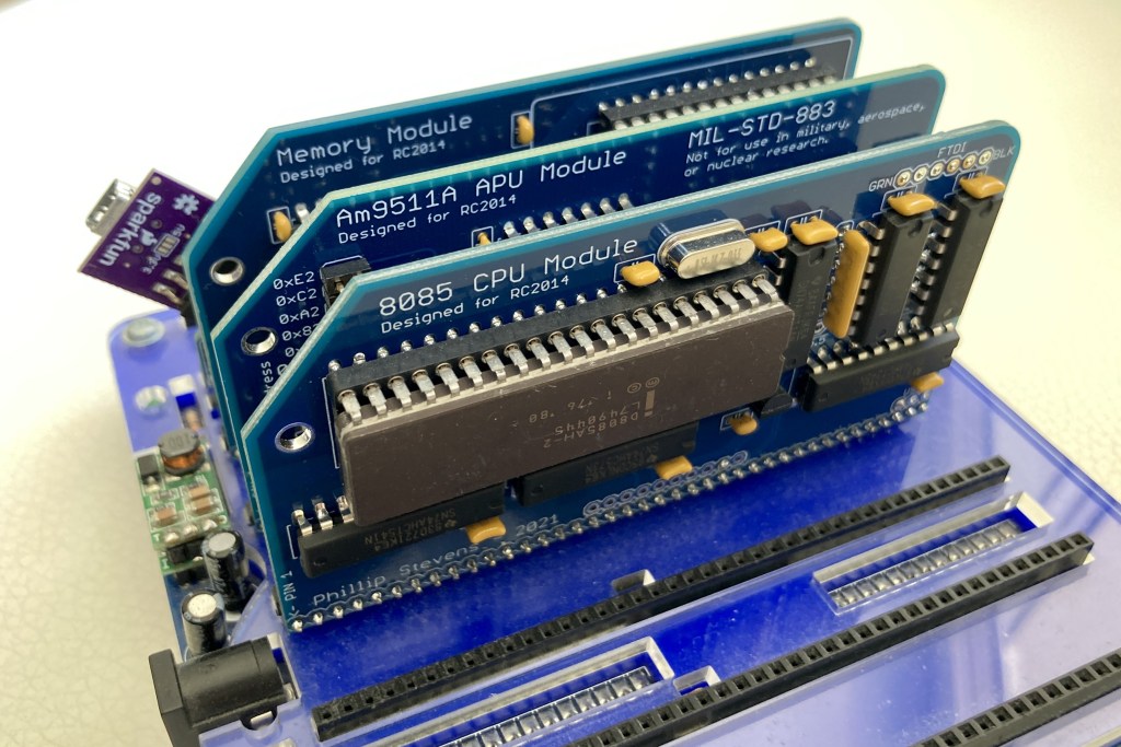
There has been quite bit of interest in assembly or machine monitors for the RC2014 lately, so I’ve taken the opportunity to write one in MS (NASCOM) BASIC which will work for RC2014 Mini / Micro / Classic ][ machines, but equally well for any machine running a version of MS Basic 4.7 or later.
The functional goal was to provide the same user tools as the NASBUG monitor, but to be maintainable and easily customisable by the user. As the monitor is written in BASIC it works equally well for both Z80 based RC2014 machines and 8085 based RC2014 machines using my 8085 CPU Module (for example).
A key issue for me was that it needed to fit completely into the BASIC program memory found below the default z88dk assembly loading address of 0x9000 for the RC2014 target.
By using BASIC language for the monitor it enabled me to focus on the functionality, as BASIC provided the command line support via INPUT(), string tokenisation via MID$(), ASC(), and VAL(), and mathematical functions.
However, Fred W. has provided a better simpler solution for getting an integer from a hexadecimal string and now that solution has been implemented.
With that key function done, then the MID$() function was used to tokenise the command string into 4 (or less) digit strings to convert into hexadecimal. Depending on the function required either signed integers were then produced to be an address or where a length was needed an unsigned integer was provided.
Finally an IF THEN tree was made to process the command string, found using the very convenient ASC() function. Since the commands are sparse, I thought that a simple decision tree would be best.
As noted, a key goal for me was that it needed to fit completely into the BASIC program memory found below the default assembly loading address 0x9000. The program fits with over 100 Bytes free, currently. But the stripped version has still over 1200 Bytes free, so there is quite a lot more code that could be added if needed.
Program Usage
The BASIC monitor is useful to casually poke around in the RAM or ROM of a running MS BASIC RC2014 machine to get a feeling of how variables and strings are stored, for example.
It can be used to enter assembled binary code into the RAM, and then run it. The assembly code can use the facilities (serial I/O, RST table, and MS Basic functions) as needed. Some further information on Assembly can be found here.
Further, it can be used together with the Zen Editor/Assembler to write and then assemble larger programs for the RC2014. When the monitor is used together with Zen, the monitor can be loaded (copy / pasted) into the BASIC Command Line, then using the BASIC HLOAD command Zen can be loaded (cat) into the RAM at 0x9000, and launched either from the monitor or directly using ?USR(0). Once editing and assembly is finished, Zen can be exited with Q and then the newly assembled program can be run from its origin by entering the monitor with run, and then E xxxx yy, where yy is a signed integer input parameter.
Using this combination of Zen and the BASIC monitor it is possible to develop, examine, and modify complex Z80 and 8085 assembly code in a very comfortable environment.
Commands for a BASIC Monitor (Syntax borrowed from NASBUG)
A – hexadecimal arithmetic
A xxxx yyyy – Responds with: SSSS DDDD JR JJ. SSSS is sum of xxxx and yyyy. Values in Hexadecimal. DDDD is difference of xxxx and yyyy, yyyy-xxxx. Values in Hexadecimal. JJ is displacement required in a Jump Relative instruction which starts at xxxx, to cause a jump to yyyy. Value in Decimal.
C – copy
C xxxx yyyy zzzz Copy a block of length zzzz from xxxx to yyyy. One byte is copied at a time, starting with the first byte, so if there is an overlap in the two areas data may be destroyed. This command is useful for filling a block with a single value. Make yyyy one greater than xxxx and put the required value into address xxxx using M. Set zzzz to the number of bytes required. Values in Hexadecimal.
E – execute
E xxxx yy – Execute program at xxxx, supplying integer input parameter yy. The USRLOC location depends on the specific MS BASIC ROM implemented. The value can be easily adjusted in the monitor source code. Values in Hexadecimal.
I – intelligent copy
I xxxx yyyy zzzz – Like the Copy command but copies to ensure it will not cause data corruption in an overlapping section. Values in Hexadecimal.
M – modify store
M xxxx – Modify memory starting at address xxxx. The address is displayed followed by the current data. The data value may then be changed. Continuous entry of new data values is supported. Values in Hexadecimal.
Q – quit
Q – Quit to BASIC Immediate Mode (Command Line).
T – tabulate
T xxxx yy – Tabulate (display) a block of memory starting at xxxx and continuing to yy-1. Values in Hexadecimal.
Further Development
As the monitor is written in BASIC it is easy to maintain for all hardware or CPU types wherever MS BASIC is found, and to further develop to support new functions. As there are about 1200 Bytes free below the default origin (in the stripped version), there is space for the user to add their own preferred functions or modifications to existing functions.
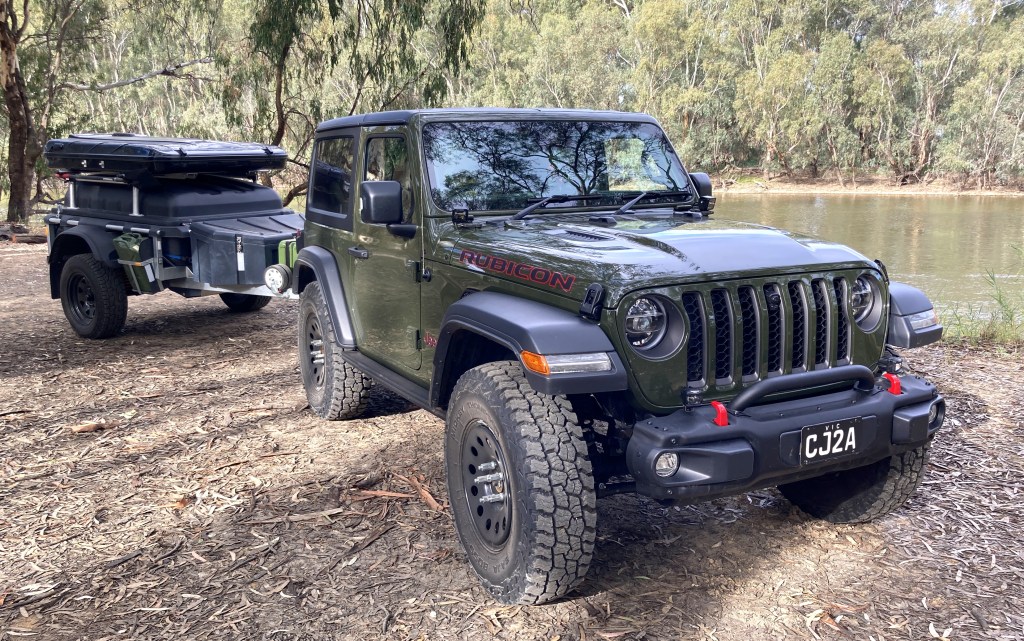
As mentioned in Curb Weight I’m using a 2023 Wrangler JL Rubicon 2 Door as my base vehicle. Without going into a lot of detail about its characteristics, it is probably themost capable off-road vehicle available off the showroom floor in Australia. So there isn’t much development required to get it prepared for overland expedition use. In fact many sources suggest that the majority of failure in overland vehicles comes from owner installed after-market options, so to minimise the expense and effort I’ll only be changing what is necessary.
At MJOC 4WD Proficiency Driver Training – August 2023
Big Dune, Big Desert State Forest – September 2023
Easter Jeep Muster, Pyrenees – April 2024
Reverting Australian “Nerfs”
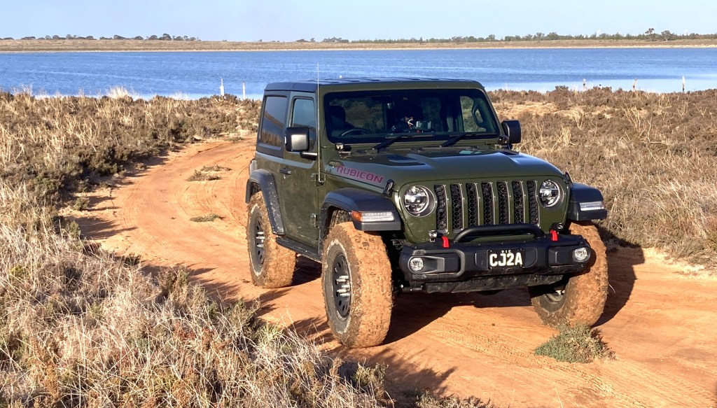
To comply with Australian regulations Jeep have made a few Nerfs to the specification for the Rubicon. These include fitting “low-rider” front guards, and most importantly fitting very small tires (equivalent to those delivered on the Sport and Sahara models). There are a few other shortcuts that need to be remedied too.
Tire Nerf
The Wrangler JL was developed to support 35″ tires in the Rubicon X model, and is delivered in the USA with 33″ LT285/70R17 tires. Yet in Australia it is delivered with LT255/75R17 tires. This directly costs 25mm of ground clearance (under the differentials), and affects entry, exit, and break-over angles.
So we’ll specify a new tire closer to the USA Rubicon X OEM specification, but more appropriate for overlanding, with the following characteristics.
Rugged Terrain (All Terrain) tire
Light Truck (LT) load specification
3 ply side wall
3PMS Severe Weather Rating
2:1 tire to wheel diameter ratio
Not wider than 10″ (255mm) – minimise mud throw – reduce rolling resistance – not attract Police attention
Reputable manufacturer
Based on the above specification the best (and only) option is the Mickey Thompson Baja Boss A/T in LT255/85R17. Since the diameter of these tires is just under 35 inches (they are also specified as 35×10.0R17LT), it is likely that the OEM suspension on the Rubicon will need extended bump stops to prevent rubbing on the “low-rider” front guards. Fortunately Teraflex produces a bump-stop extension kit which reduces the upward travel by just over 1″, which is enough to prevent rubbing.
As an option, the Kenda Klever R/T KR601 and Kenda Klever M/T2 KR629 are available in 35×10.5R17LT and they also qualify based on my above requirements. The 35×10.5R17LT size is slightly larger than the LT255/85R17, being a true 35″ tire, and would therefore provide greater ground clearance.
The tires are mounted on Mopar Winter Wheels from the Wrangler JK range, supplied on special order from Jeep Australia. These wheels are the same width and offset as the originals, but protect the valve stem much more and seem more robust than the alloys supplied as standard. The Winter Wheels will fit all the Wrangler JL trims, but not the JT as the Gladiator rear disk rotors are too large to fit inside the wheel.
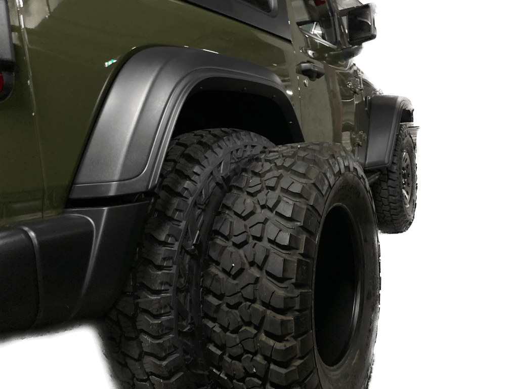
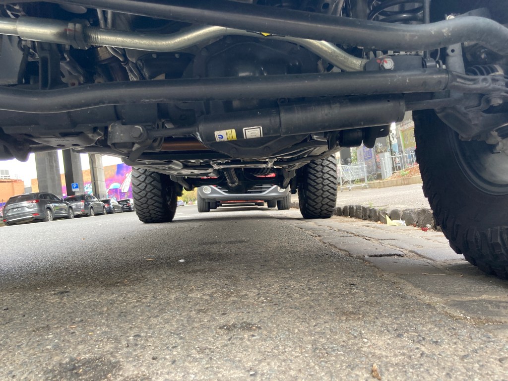
Steering Damper Nerf
When converting the Wrangler JL to Right Hand Drive Jeep placed the steering damper under the track bar (panhard rod), causing it to be a full 50mm under the lowest point of the suspension. Owners who take their Wranglers off-road always damage the steering damper and it can get hooked up on the large attachment point hanging under the front axle.
Australian OEM steering damper location.
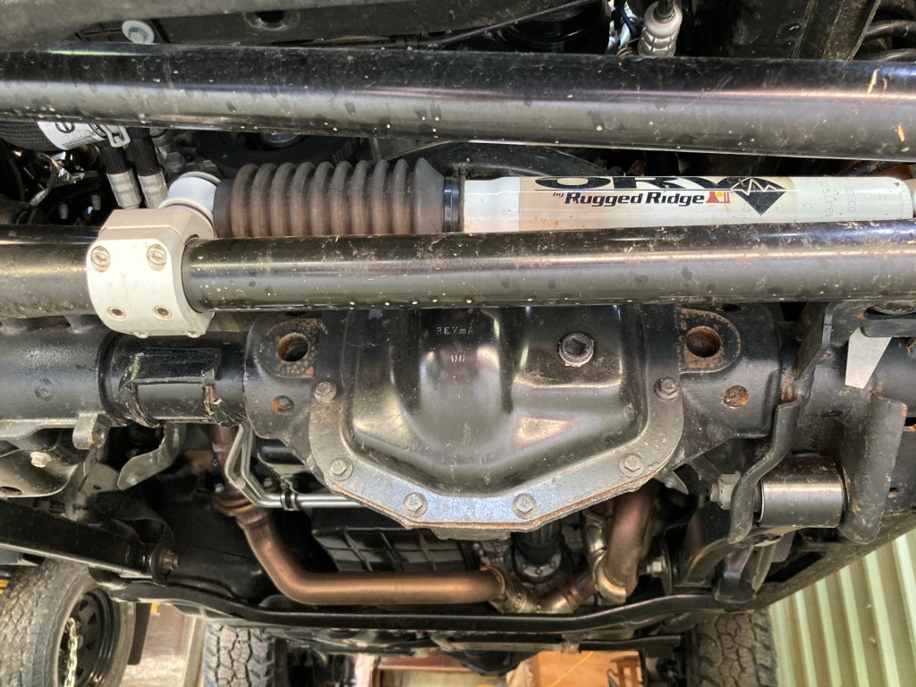
The recommendation is to use a Teraflex steering damper relocation kit to move the damper above the drag link and out of the way of harm. Together with the relocation kit it is necessary to add an aftermarket steering damper. The brand doesn’t matter too much but for the record, I used an ORV Rugged Ridge steering damper originally for a JK Wrangler.
Relocated steering damper, with “clubfoot” removed.
After relocating the steering damper, the large mounting point hanging under the axle can be cut off with an angle grinder / cutter. With a fairly neat set of cuts about 2kg of metal comes off the front axle which improves ground clearance and helps with reducing unsprung weight.
Rubicon Caster Reset
The Wrangler JL Rubicon is lifted by over 1″ over its sister models. This provides the space for larger tire sizes, but in doing the lift Jeep did not rework the control arms to retain the designed front wheel caster.
Specifically the JL Sport and many other cars use over 6 degrees of caster to stabilise the steering. Caster also has the positive side effect of improving cornering by increasing the steering angle of the tires. However, after the OEM JL Rubicon lift is fitted the resulting caster is only about 4.5 degrees.
Fortunately Mopar produces an extended front lower control arm which is 1/4″ (6mm) longer than the standard length lower control arm. This was produced as part of its Mopar 2″ lift kit. Fitting these extended lower control arms returns the front wheel caster to 5.5 degrees. This quietens the steering and makes the driving experience much more relaxed.
Suspension Improvements
Noted above are the extended front lower control arms and the extended bump stops, so the only additional improvement is the addition of heavy duty shock absorbers (dampers). The majority of protection required will be on corrugated roads, where the suspension travel is minimal and high frequency. This means that external reservoir dampers, which are designed for long travel situations (like a Baha race) are not the best solution. For the Australian outback I have selected to use the Ironman 4×4 Foam Cell Pro dampers. These dampers are the traditional robust twin-tube design (not pressurised), built with huge oil reserves and very solid (rebuildable) construction. It is also worth noting that they extend the axle droop by over 2″ over the standard dampers, as they are specified for a 2″ lift kit. The extended droop makes both axles more compliant to the terrain, and more than compensates for the reduction in upward travel through the extended bump stops.
As the ball weight of my trailer combined with the load of equipment will add about 260kg to the rear of the vehicle, it is necessary lift the rear when fully loaded and yet allow the full travel and comfort when the vehicle is used for rock crawling day trips. The ideal solution for this is to use Air Bag suspension assistance, which allows adjustable support up to 400kg. I’ve fitted AirBag Man Heavy Duty airbags and run them at 40 psi to 45 psi when towing and 5 psi when not.
Towing System
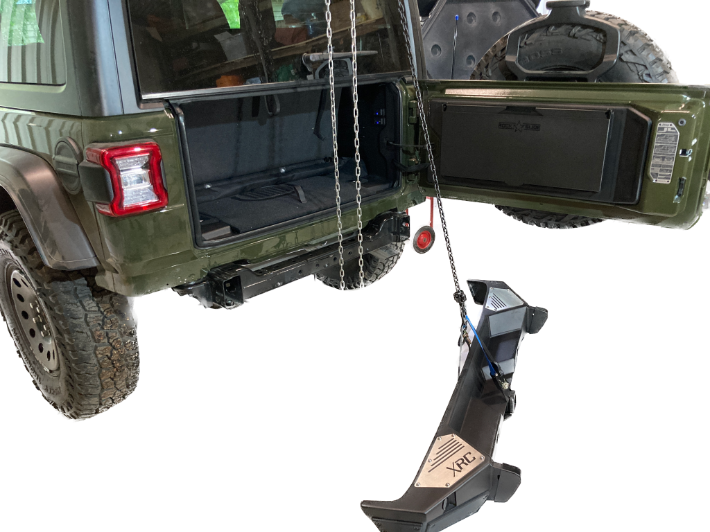
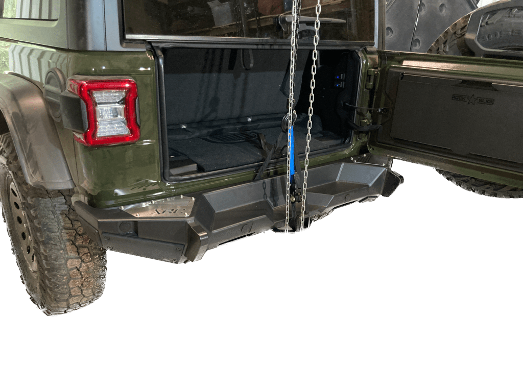
The Wrangler Rubicon has a very light weight plastic rear bumper bar. The OEM tow bar is fitted underneath the bumper on a chassis cross member with 4 high tensile steel bolts. The rear recovery hook is bolted to the chassis with 4 high tensile bolts.
To provide a solid towing and recovery platform the rear bumper and hook were removed and a Smittybilt XRC Gen 2 rear bar was fitted. This bar is bolted to the chassis with 12 high tensile steel bolts, 4 in the normal OEM tow bar location, and 4 at each chassis rail. The bar itself weighs over 48kg, and provides a Class 3 Receiver and two recovery and high lift jack points.
Removing the OEM rear bumper necessitates relocating the number plate. The relocation was done with a combination of the included Smittybilt product and an ARB number plate relocation kit.
Trailer wiring for Australian (APAC) vehicles is different to the American (NAFTA) solution. The NAFTA Jeeps do not have a separate brake and indicator system; their brake light is flashed as an indicator. So purchasing a NAFTA Trailer Wiring System is not going to work. The best solution is the purchase the Australian (APAC) Trailer Hitch kit (MOPAR Part Number LA82210162) directly from a dealer. The Australian Trailer Hitch kit includes a 2″ drop tongue, 50mm ball and Australian 7 Pin Flat Trailer Connector, as well as an OEM hitch point (which I have not used).
The international Trailer Brake Controller (MOPAR Part Number 82215652AD) kit works well with the Australian Trailer Hitch kit. The control knob fits nicely into the dash, replacing the 12V cigarette plug, and the ECU can be stuffed up into the space behind the panel in the passenger footwell.
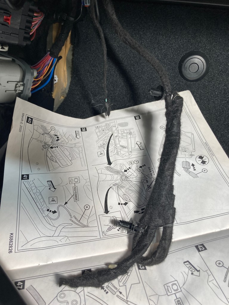
Fitting the Australian Hitch kit meant passing the trailer wiring INSIDE the vehicle (like the Quadratech video) not outside according to the instructions and routing the wiring through dash behind the ICE head unit and down into the LHS (passenger) footwell to mate with with the Trailer Brake Controller and its wiring.
The accessory wiring and Trailer Brake signal wire are both found in the LHS footwell. From the LHS footwell the power supply for trailer lighting and trailer brake can be (optionally joined to one supply and) passed through the firewall into the LHS front wheel well and so to the battery.
Accessory AUX connection & Trailer Brake Signal Wire found in LHS footwell.
Other Things Worth Mentioning
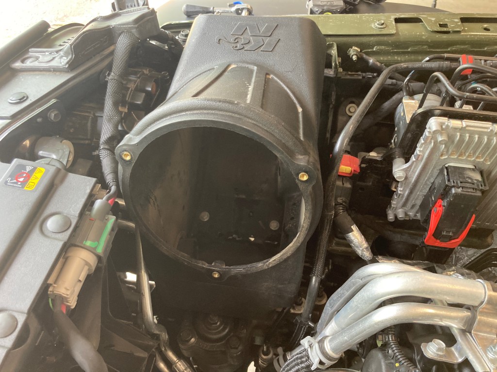
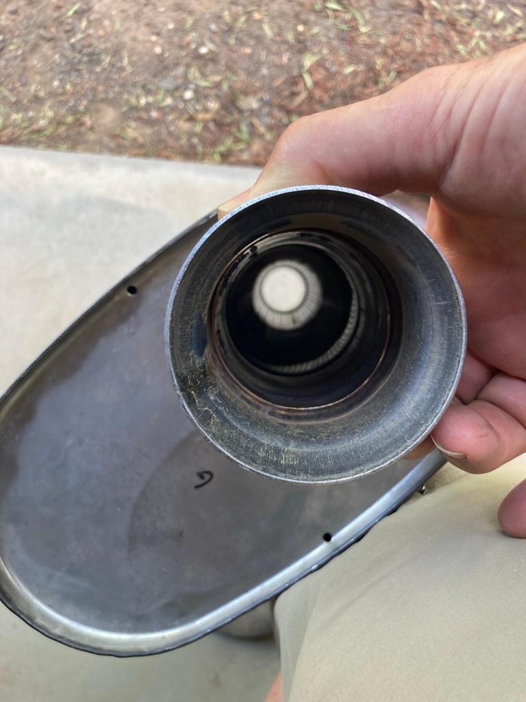
Cold Air Intake
Added a K&N air box and filter kit, and integrated the OEM cold air intake into the bottom of the K&N air box by cutting off the curved end of the CAI and cutting a matching hole in the side of the K&N air box. As the K&N filter can be easily cleaned and renewed anywhere, it is ideal for use in dusty outback conditions.
OEM CAI pipe inserted into base of K&N air box.
Taser JL Tuner
A Taser JL Mini allows the tire size and many other settings to be done at any time. It also provides live info on the manifold vacuum and does light shows when needed.
Fitted Rubicon 392 Gear Shift Paddles to steering wheel. Very useful off-road, for keeping both hands on the wheel.
Also on the tail-gate there is a Rockslide Engineering table, and some additional 12V connectors and USB connector power supplies.
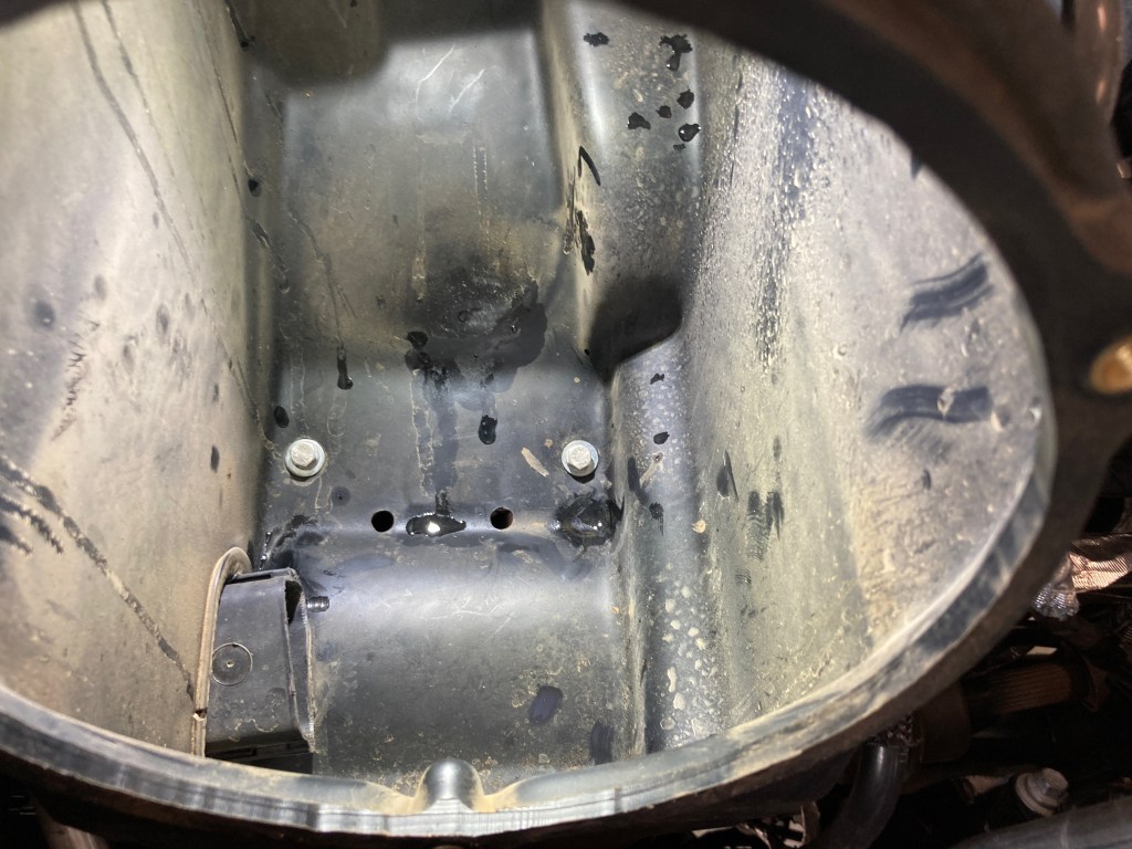
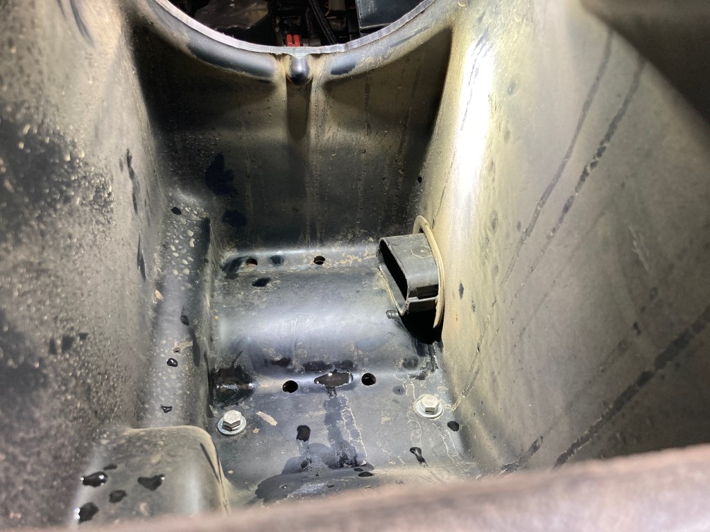
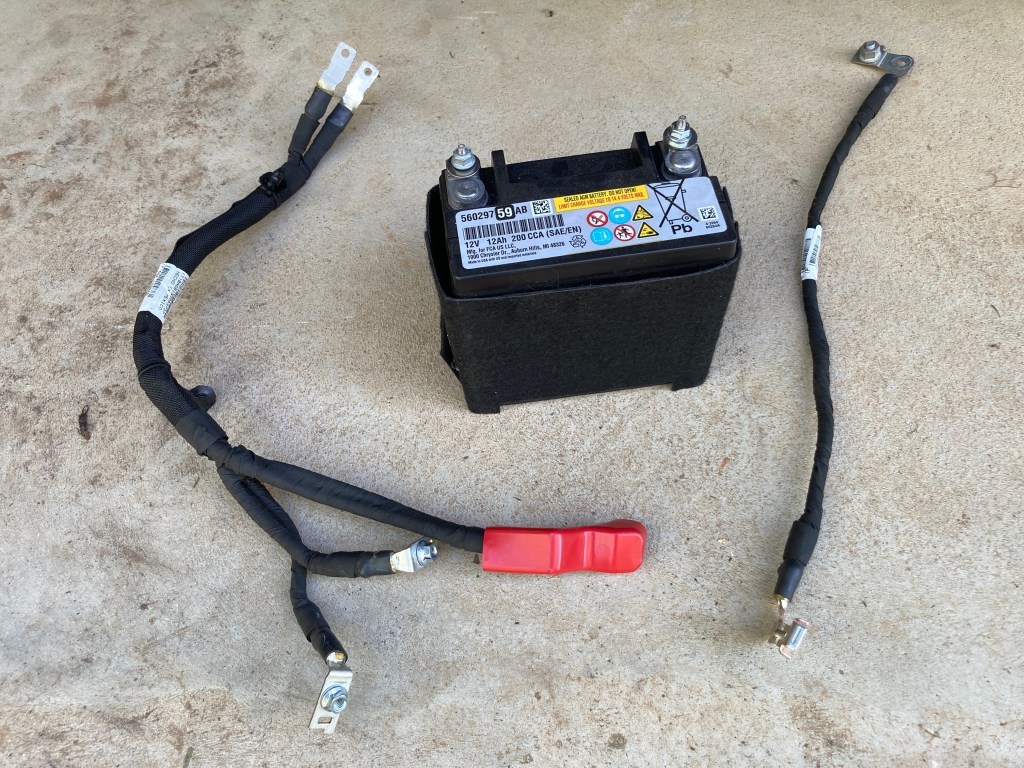
ESS Battery Delete
I’ve removed the small 12V ESS auxiliary battery (saving over 5kg), and all associated wiring, leaving just the disconnected PCR relay signal wires in place to ensure there are no ECU codes generated. Bridging N1 and N2 in the power distribution centre ensures that normal service for all power systems is retained, even the ESS function (although I keep ESS switched off).
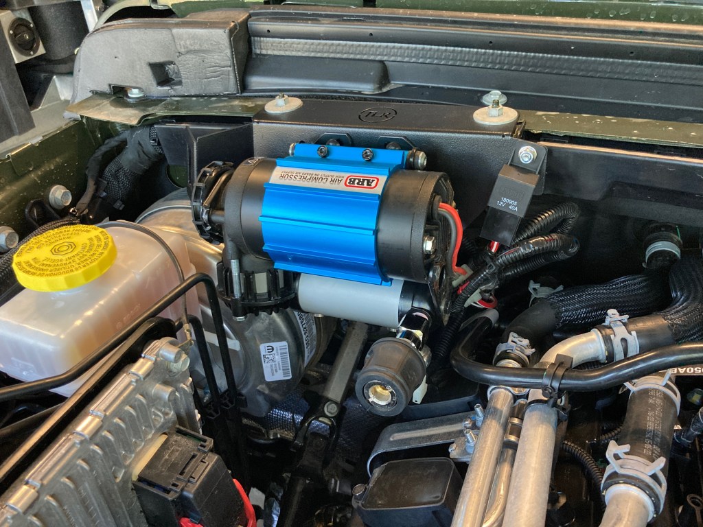
ARB compressor on TLR mount specific to RHD JL/JT.
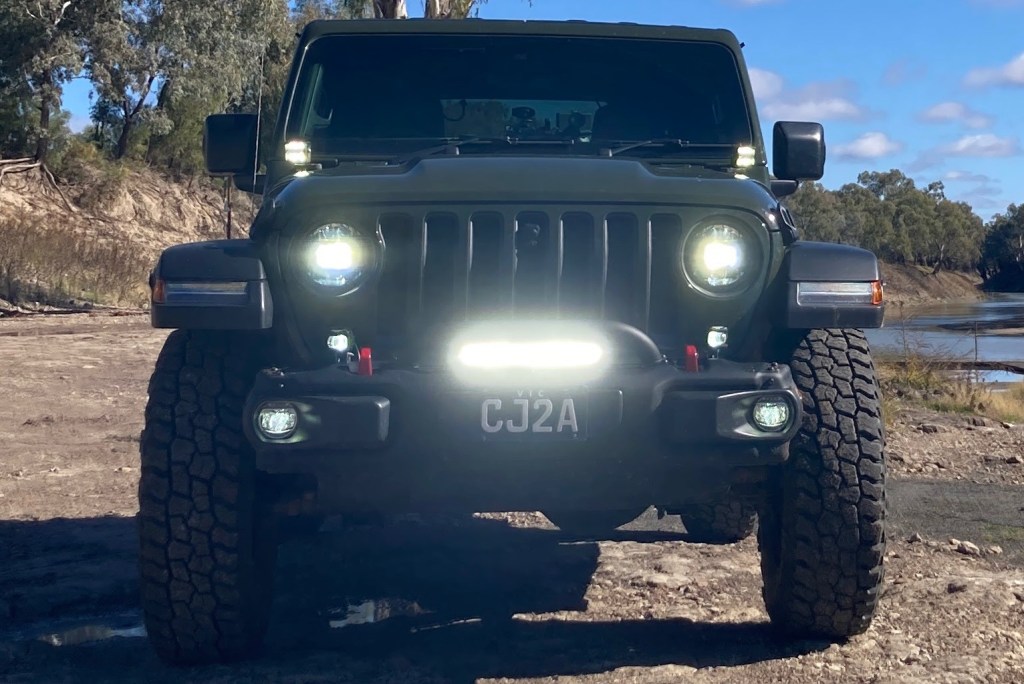
Front Lighting
Added front lighting to; 1. Provide around corner trail and work cube lights to A-Pillar mounts. 2. Improve spread and range of fog lights with letter-box lights. And 3. Enhance high beam fill with a spot bar. Each of these light improvements are modest, and importantly being small they don’t block airflow to the engine or transmission radiators.
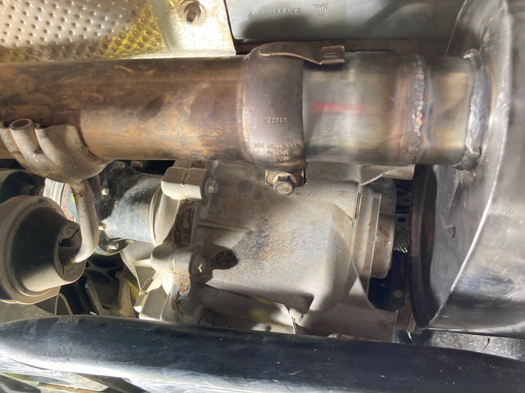
Exhaust System
Added a Borla Climber exhaust in the Touring version. This exhaust moves the muffler forward of the rear axle to increase departure clearance (though the rear bumper still determines the ultimate departure angle). The Climber exhaust system is 7kg lighter than the OEM exhaust and moving all the muffler weight forward of the rear axle is a useful result.
Interestingly, fuel economy also seems to be substantially improved, probably because the straight-through Borla Climber muffler is reducing cylinder back pressure. On a standard journey (of known distance and speed), improvement by over 1.5l/100km was posted, off the OEM base economy of 12l/100km.
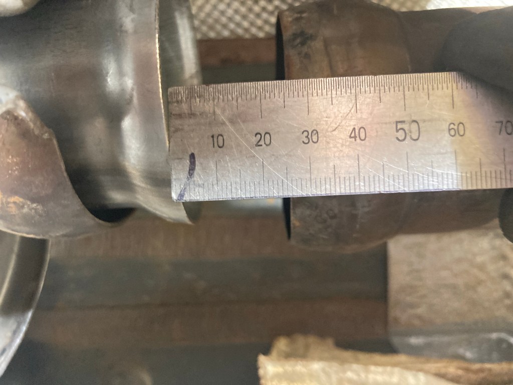
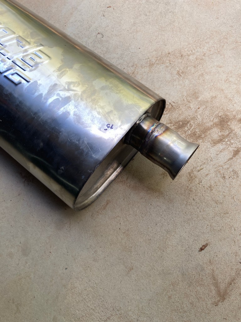
35mm gap to clear transfer case housing.Extended front pipe.Straight through.Fitting with extension showing clearance to transfer case.Fitting with shortened tailpipe flange.Tailpipe.
Unfortunately the 2DR version of the Borla system doesn’t fit the Rubicon RHD version precisely, and the muffler needed to be relocated 35mm to the rear to clear some protruding sections of the transfer case housing. This was done by extending the muffler front pipe and shortening the tailpipe flange, each by 35mm.
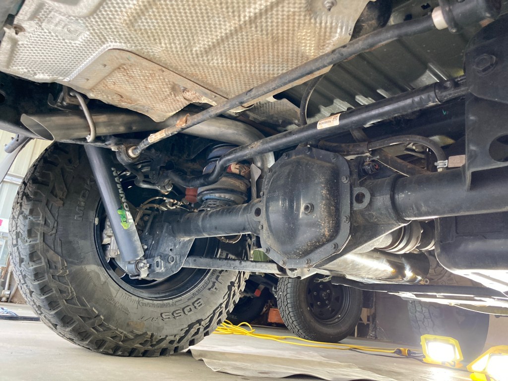
Regearing and TORSEN Differential
Recently, I’ve regeared the differentials to 4.88:1 which helps to run regularly in 8th gear when towing. Now 100km/h is set to 2,000 RPM in 8th, or 2,500 RPM in 7th if it is hilly. The overall lowest crawl ratio becomes 93:1, and this changes normal 20 deg plus hill ascents to 4th or 5th Low Range. This adds substantial flexibility in choice for climbing gears and crawling technical tracks.
Lastly, I’ve swapped the rear Jeep eLocker differential for a TORSEN differential. More in this post.
Karl (of Karl’s Diffs) did both TORSEN and regearing installations. Both installations had their quirks and took longer than expected, and so are best done by experts, like Karl.
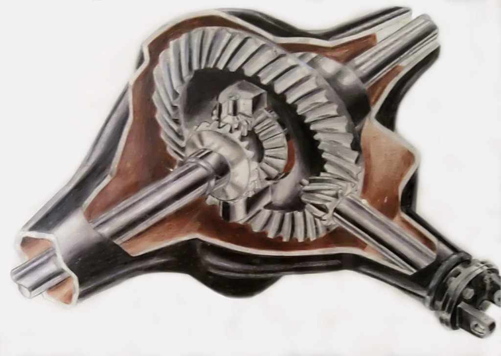
There are incorrect views about open differentials in the Internet. To this point specifically, a cross-axle open differential provides exactly a 50/50 torque split between each half-axle at all times by design.
Open Differential – Cut Away View
The differential’s role is to allow each half-axle to travel at different speeds, but the torque split across the half-axle ends is always equal, set by the ratio of the pinion and side gears.
You can Google that “torque split open differential” and there are lots of articles describing the mathematics and engineering behind this fact. Here is one, and here’s another, for example.
If one driven wheel loses traction there is no “torque leakage” out of that wheel. In fact the overall engine torque delivered (or load) drops immediately to zero (excluding parasitic drive-train friction). This is why the engine will rev-up (become unloaded) when a wheel(s) loses traction.
You can test how much reaction torque a free-wheel can produce in your garage by jacking up a front wheel (in 2WD) and using a torque wrench to attempt to loosen the wheel nuts. Measure how much torque you can achieve. This demonstrates that a free-wheel cannot produce a torque reaction.
Traction Control systems and clutch based LSDs use this equal torque split across the half-axles to generate traction, by adding brake friction torque to the free-wheel on the half-axle. This allows the engine to deliver torque to the free-wheel axle and, by design, exactly the same amount of torque to the other half-axle (with the wheel with traction) allowing the vehicle to proceed.
There are only two cases, I’m aware of, where the 50/50 split across the differential half-axles is not designed in. One in the centre differential of various Mercedes Benz AWD systems, where the axle side gears and pinions are built with different numbers of teeth to provide a torque bias to the rear (e.g. 60/40). The other is in Torsen differentials (such as Quaife, Peloquin, Eaton Truetrac brands) which use worm drive mechanics to multiply the torque (described as torque bias ratio) across the differential center.
Anyway, I just wanted to share that since the “torque-leakage” myth pops up all over the place and it is best to put an end to it.
In my previous post on Sleeping Arrangements, I was fairly negative about Roof Top Tents (RTT), citing their detrimental effect on vehicle driving dynamics, vehicle aerodynamics, and also the potential fall danger of sleeping over 2 metres above the ground at the end of a flimsy ladder.
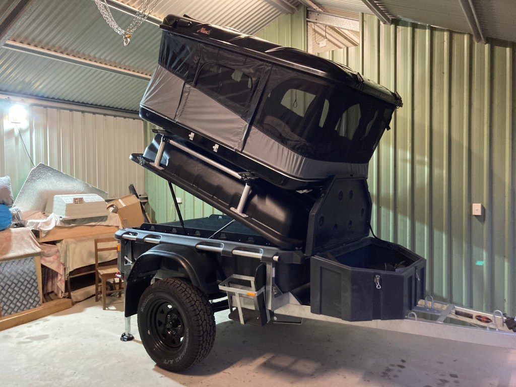
However, I’ve now decided to mount a RTT to the top of my Stockman Pod Extreme. Essentially because mounting the RTT on the trailer removes all of the above mentioned disadvantages, but keeps all the RTT advantages.
The mounting height is less than 1.5 metres above the ground and is barely 40 cm above the top of the trailer load platform. Whilst the 60 kg of the RTT will affect the trailer dynamics, in the case where the trailer cannot follow along, it can be left behind at camp leaving the vehicle dynamics unaffected. The highest point of the RTT is lower than the vehicle roof line, and the selected RTT is quite streamlined, so the overall aerodynamics should not be significantly worse than they already are (considering both vehicle and trailer are pretty much brick shaped anyway).
The most important benefit of fitting the RTT to the trailer is that at just 1.5 metres off the ground a fall is substantially less dangerous.
To further reduce the danger of falling, I’ve decided to fit my RTT so that the entry will be from the rear using a set of well formed, large and stable steps. This rear entry concept does have an impact on the method I’ve chosen to fit my RTT to the trailer.
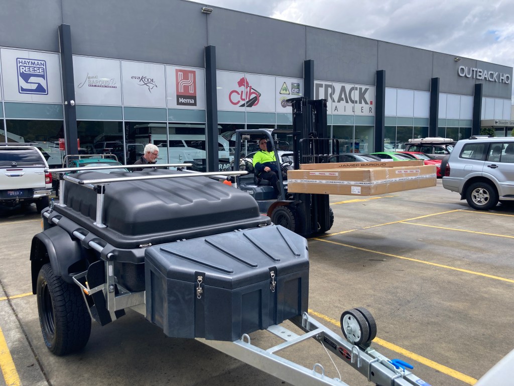
I’ve chosen to use a James Baroud Evasion M Evo, based on good reviews and inspecting the options available at retailers around Melbourne. I purchased my RTT from Outback HQ, and I’m very happy with their customer service.
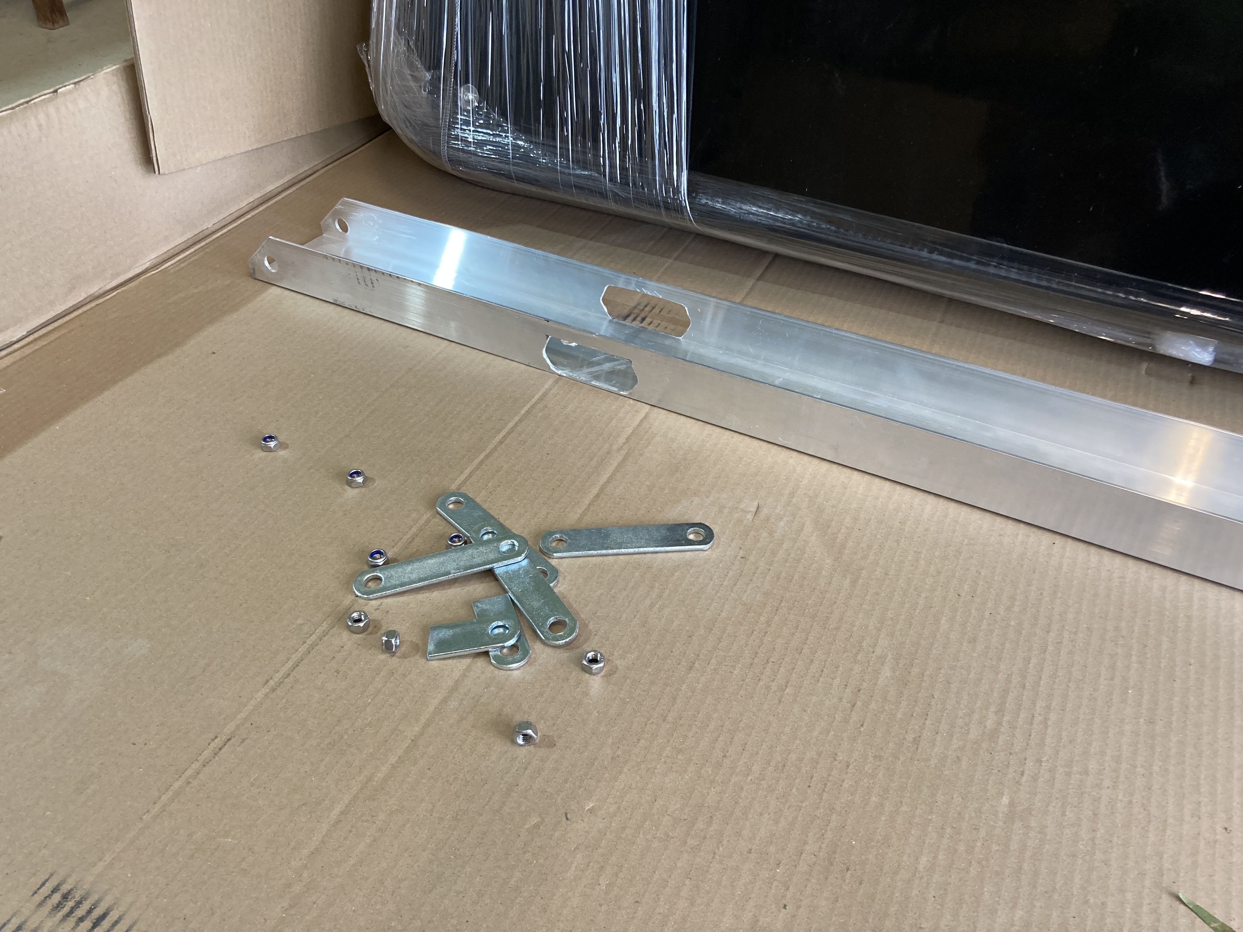
Taking Delivery
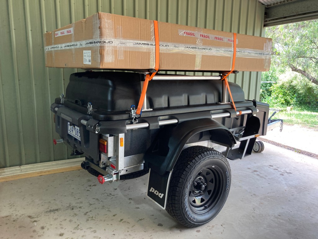
Following delivery of my Stockman Pod Extreme, the large cardboard box was placed on top and secured for the drive home.
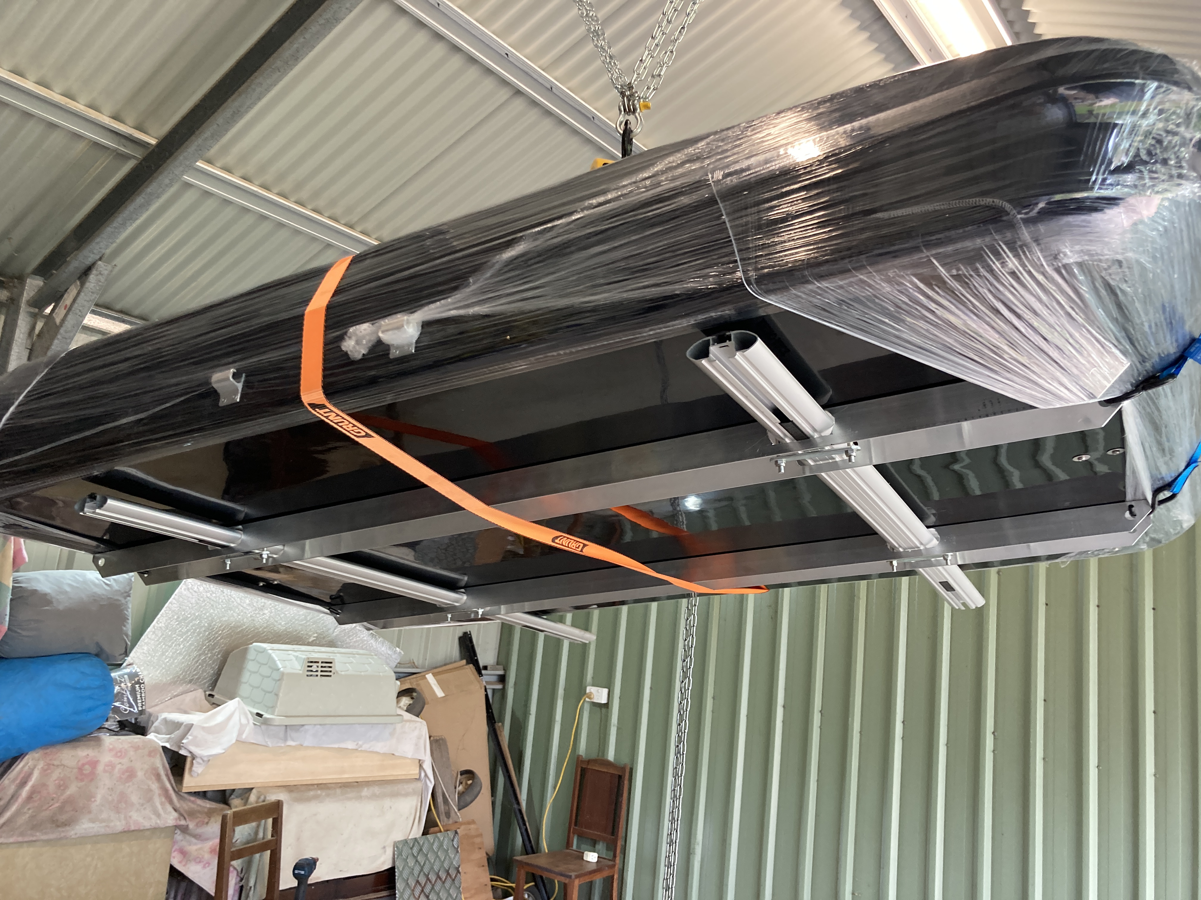
Fortunately there was no further excitement until I was able to crane off the RTT and get to work mounting it.
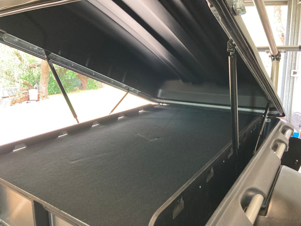
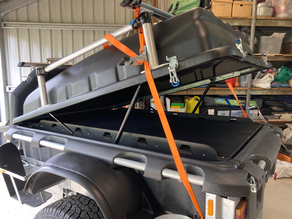
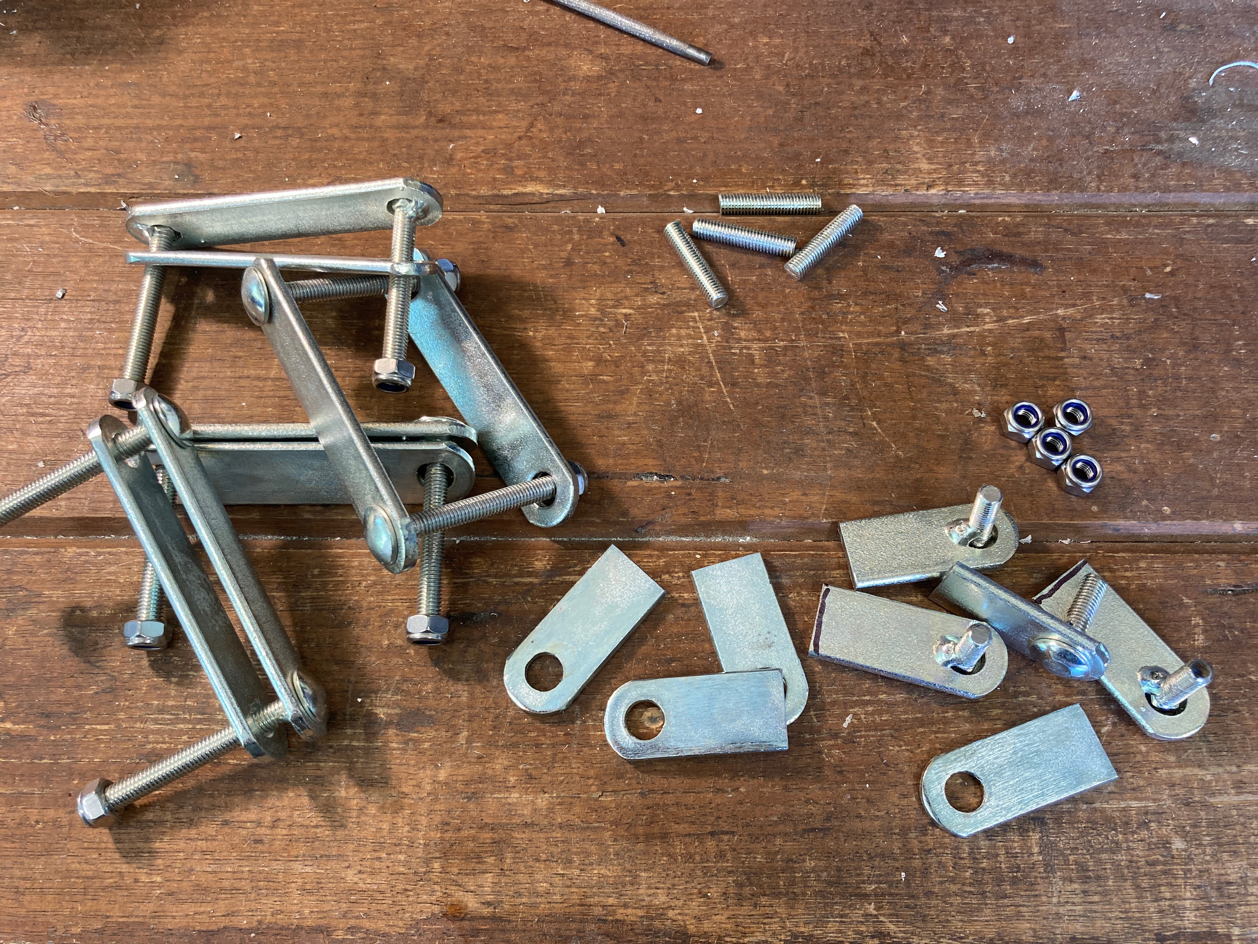
Firstly the Stockman Pod Extreme RTT Upgrade gas struts needed to be attached to their mounting points in the lid of the trailer. If they weren’t added before the RTT was fitted then the smaller standard struts (which remain) wouldn’t be able to lift the lid with the tent. Adding the heavy duty struts costs some access to the trailer, by reducing the angle of the lid, but it is not significant.
However, with the heavy duty gas struts in place, the lid needed quite some encouragement to close. I needed to juggle ratchet straps to close it down.
Rear Entry Reinforcing
Usually Outback HQ recommends that the James Baroud M sized tents need just two bars, but they should be widely separated. Larger sized RTTs need to have three bars to support them properly.
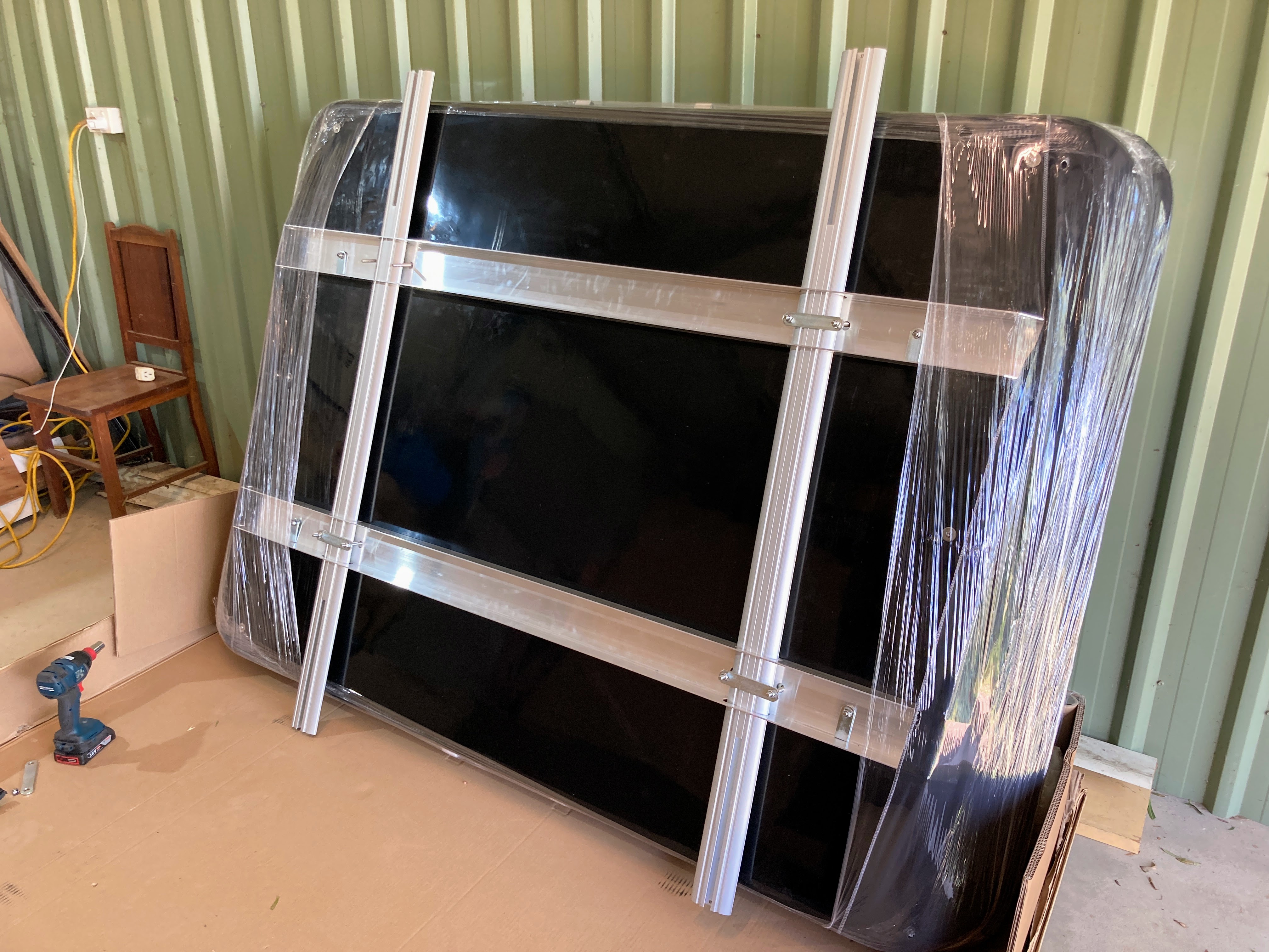
With the Stockman Pod the Rhino Aero bars are just 1.5 metres apart, which is quite close but not an issue normally. However, as I was planning to use the rear entry of the James Baroud Evasion RTT there would be quite a lot of load over the end of the tent, out beyond the internal aluminium rails integrated into the tent under-shell. This could lead to cracking the outer shell in the worst case.
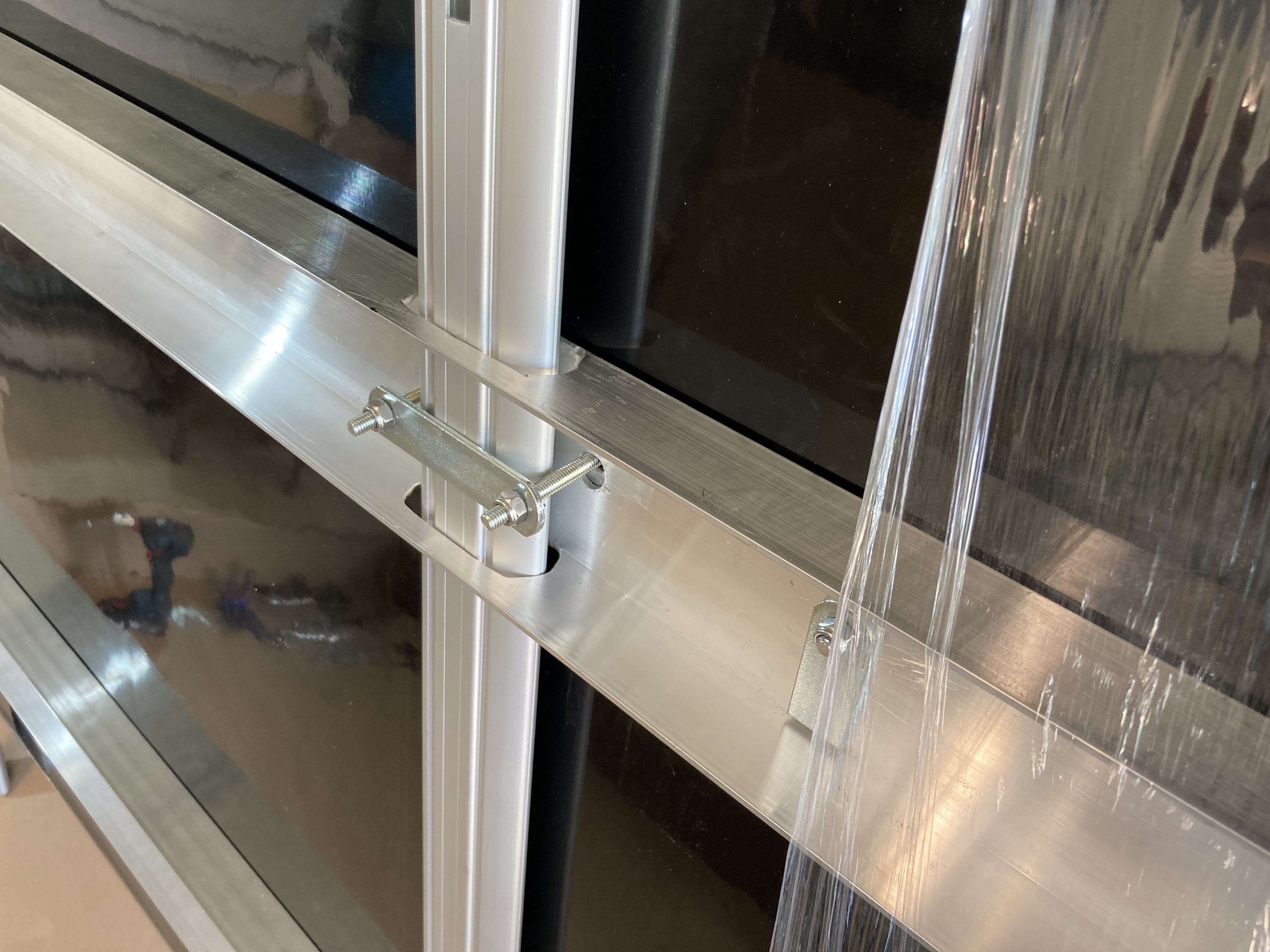
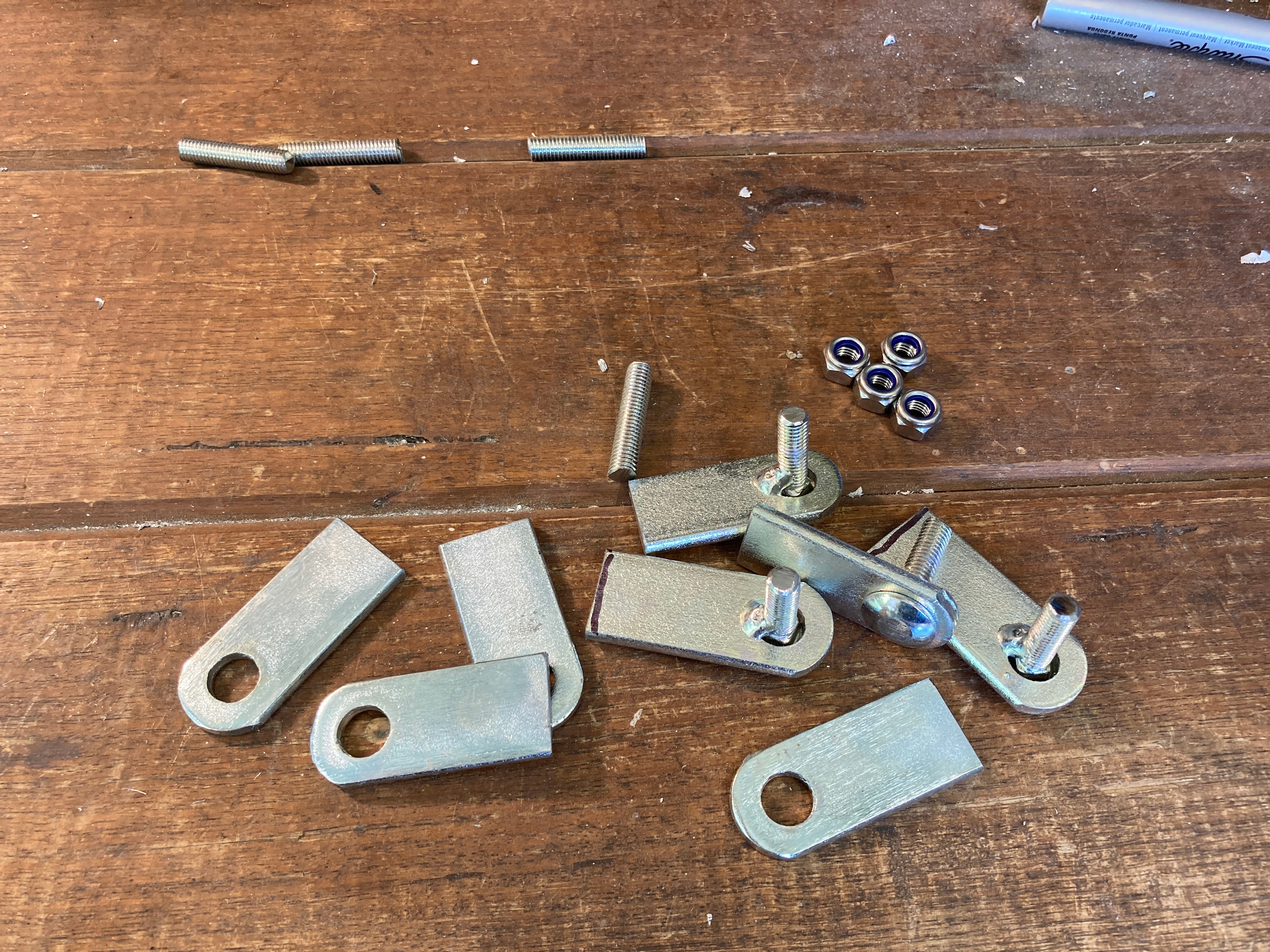
To provide an additional layer of strengthening to both front and rear of the RTT, I have added full length aluminium beams under the existing integrated rails but extending to the end of the tent shell at both front and rear. This provides full support for sitting on the rear ledge of the tent (when entering or leaving), and also provides additional strengthening for the entire mounting system.
I chose to use 100mm x 50mm x 3mm thick aluminium channel. This is the largest channel shape that can fit between the top of the Stockman Pod Big Top Lid and the top of the Rhino Aero bar on which the RTT would be mounted. As the Aero bar is only 40mm thick, this left 10mm of material on both sides of both channels to provide the end-to-end strength that I desired to achieve.
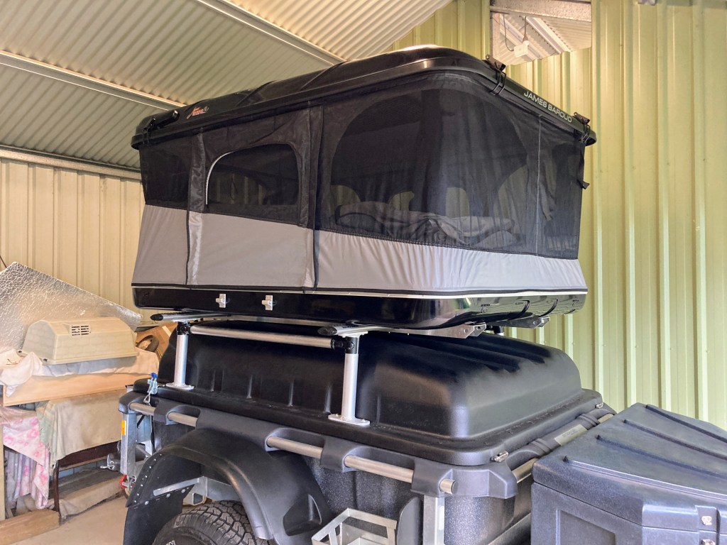
Overall, this mounting method adds significant strength and security to the whole build. The RTT cannot “lift off” the bars, as the Aero bars are inserted through the channel rails which are tied at multiple points to the RTT chassis rails.
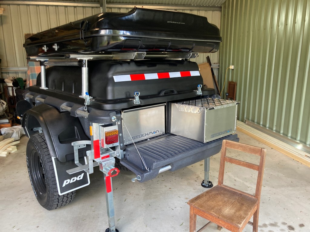
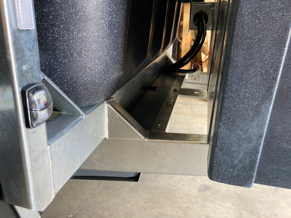
Now the trailer lid can be comfortably opened and closed with the RTT fitted, either stowed or open. With the RTT stowed or even opened, the front tool box can be opened too.
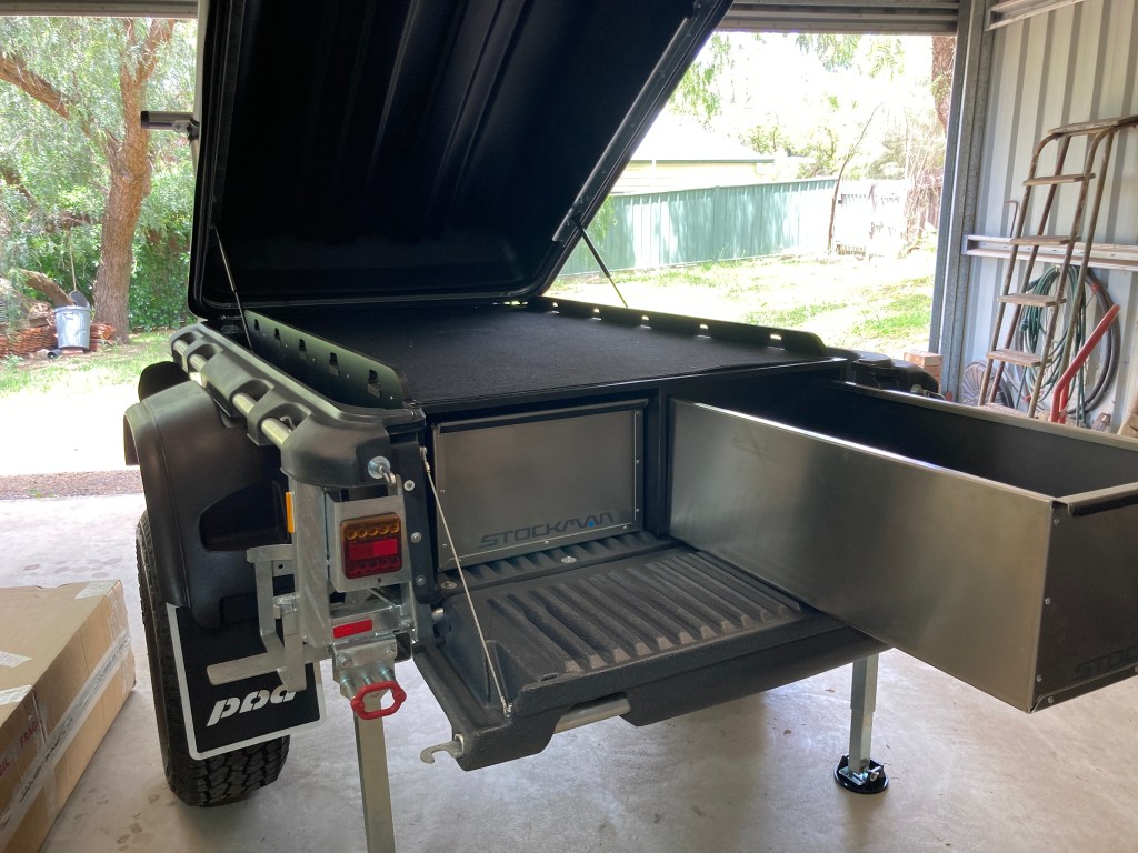
Building Rear Step
My Stockman Pod Extreme is fitted with the plywood storage shelf and two aluminium storage bins, as well as the standard fold down tail-gate. These conveniently provide two large and stable steps up to the RTT. In addition only a low stool or step is needed for the first step up to the tail-gate.
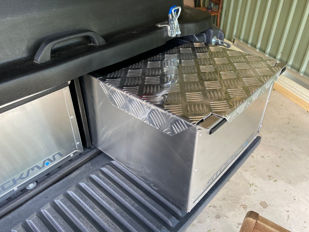
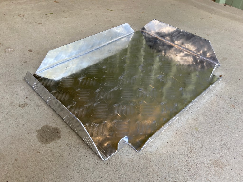
So all that was needed was to turn the top of the storage bin into a large step. This was done with a sheet of 2mm thick aluminium non-slip tread plate, carefully cut, and folded for strength, and fitted across the top of the storage bin. As a side benefit, the aluminium step can be stored in-situ on the storage bin so it takes no space to transport.
Obviously, the wooden school chair photographed is not a permanent solution. I will get a work step or stool that can be used to provide one or two steps up to the tail gate. The tail gate makes a safe stoep to leave boots and mud before stepping up into the RTT via the storage bin step.
To exit the RTT it is just a matter of sitting on the edge of the tent shell and your feet naturally find the top of the storage bin step, and you can stand up (preferably holding onto one of the tent roof struts for stability), before stepping down to the tailgate. It is even possible to sit on the storage bin lid when pulling on boots.
I would also point out that the aluminium storage bins are 2 metres long, and are contained within a structural case. The storage bins are designed to hold well over 100 kg of items. The step could be used with the storage bin extended by over a 1 metre (rather than just the depth of the tail gate, about 40 cm). So, the step is quite strong and overall using this rear entrance to the RTT is much safer than the standard folding aluminum ladder.
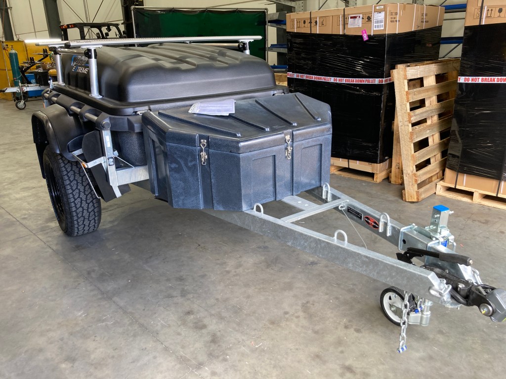
As discussed in the Curb Weight post, I decided to purchase a custom built Stockman Pod Extreme for Going Bush. I took delivery of following a short delay because I asked to add Rhino Rack Aero bars and upgrade the lid to support a roof top tent.
This is a short note to cover the adjustments that I made to the standard Stockman Pod Extreme product, that do not appear on their options list, and later modifications.
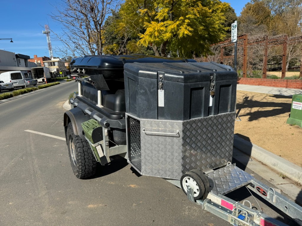
I’ve added a few things since this post was originally written. Most obviously the 160 litre fuel bin under the tool box.
A video can be seen here.
20,000 km Review
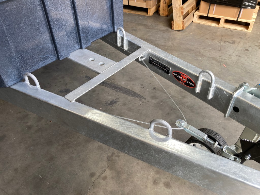
Drawbar Tiedown
To use the drawbar to carry light weight items such firewood or rubbish, added 4 D-ring tie-down points welded to the inside of the bar. This will enable the load to be secured on the top of the drawbar, and therefore not need to pass under the bar where the tie-down strap could be cut or scraped on a rock. The tie-down points are also set up enough to allow a PVC or steel pipe to pass through them, potentially allowing a hammock style carrier to be created for smaller items.
Frame Gusset
I added a gusset between the frame and drawbar. Stockman have never seen a case where separation was a problem but, since it was easy to do and it made me happy, it was done.
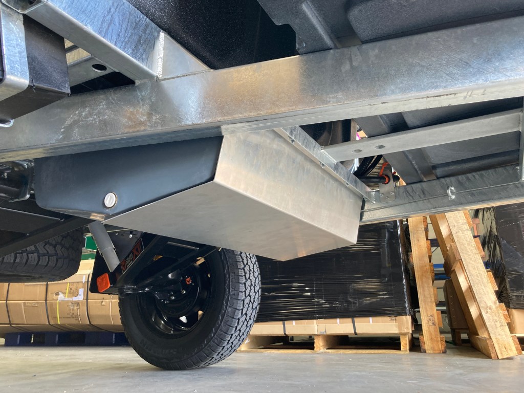
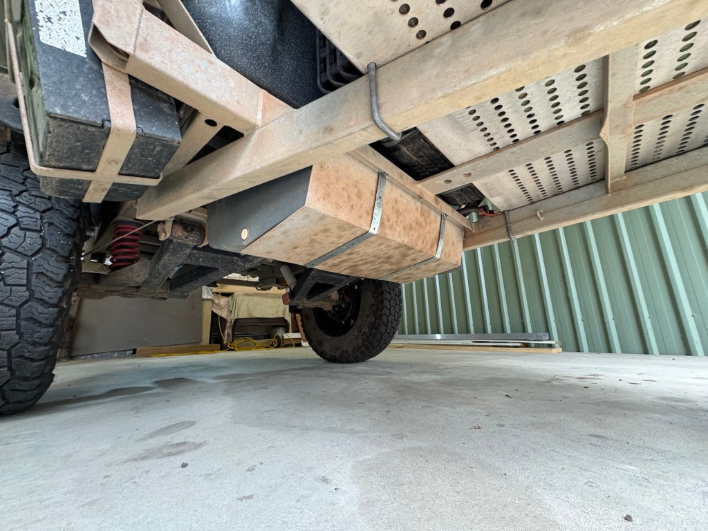
Water Tank Stone Guard
The Stockman water tank is 6mm thick poly roto-moulded plastic and it is very tough, well able to withstand blunt trauma from rocks and other material. It is also located much higher than the tow vehicle ground clearance. So there is little that can go wrong.
But to prevent damage due to sharp objects, such as branches and sticks, I’ve added an aluminium bash plate to the underside of the water tank. This is not to prevent normal impacts from being absorbed by the poly plastic tank, but rather to prevent a sharp object from penetrating the plastic. The concept is like lightweight medieval chain-mail used to prevent cutting and stabbing, rather than full plate armour.
The stone guard is very effective at preventing stone damage, but it does suffer from damage itself. The continuous stone impacts cause the underside protection to hang down, because the leading side is being made concave by the impact. So I’ve tied the guard up with some lightweight galvanised steel. This will prevent the guard hanging down as it does its job of protecting the water tank.
Stone Guard Ties.
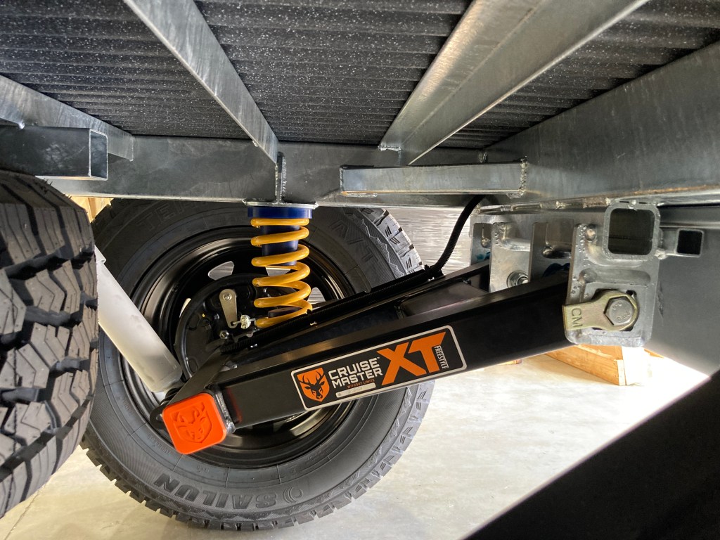
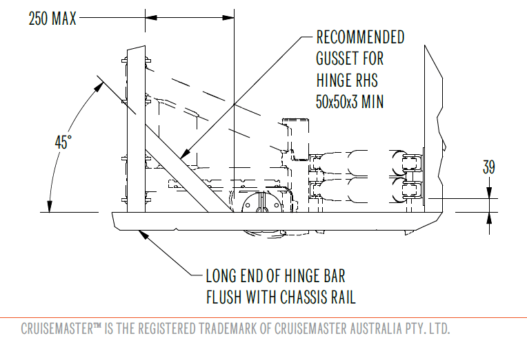
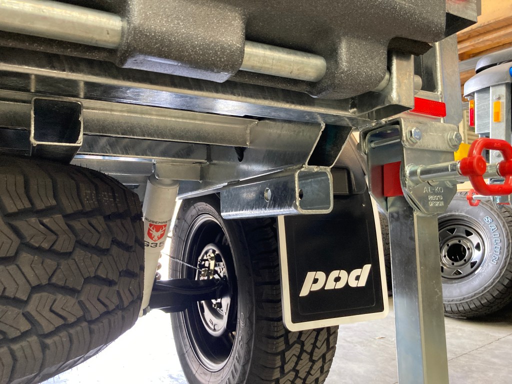
Suspension Reinforcement Bracing
Triangulation gussets between the suspension hangers and the spring mounts was added as per the CruiseMaster installation recommendation. Prior to my build this was not being done but now it has become standard practice for Stockman to add the triangulation reinforcement bracing.
Hayman Reece Recovery Points
And finally, the standard D-ring recovery points were replaced with Hayman Reece 2″ hitch points. This allows recovery straps to be connected to the hitch point with standard hitch pins, rather than using a shackle. Also each Hayman Reece hitch can support other accessories, such as a vise mount for example. Using two hitch points allows recovery forces to be shared onto both side of the frame, and allows the trailer to be guided more accurately for a reverse recovery.
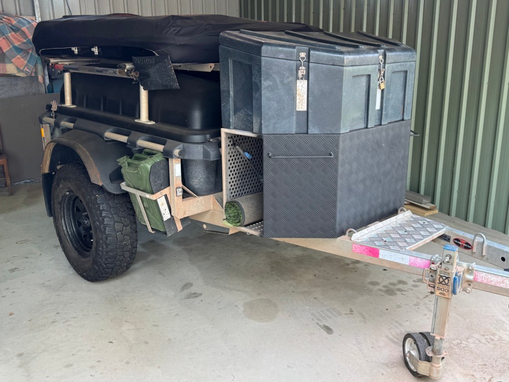
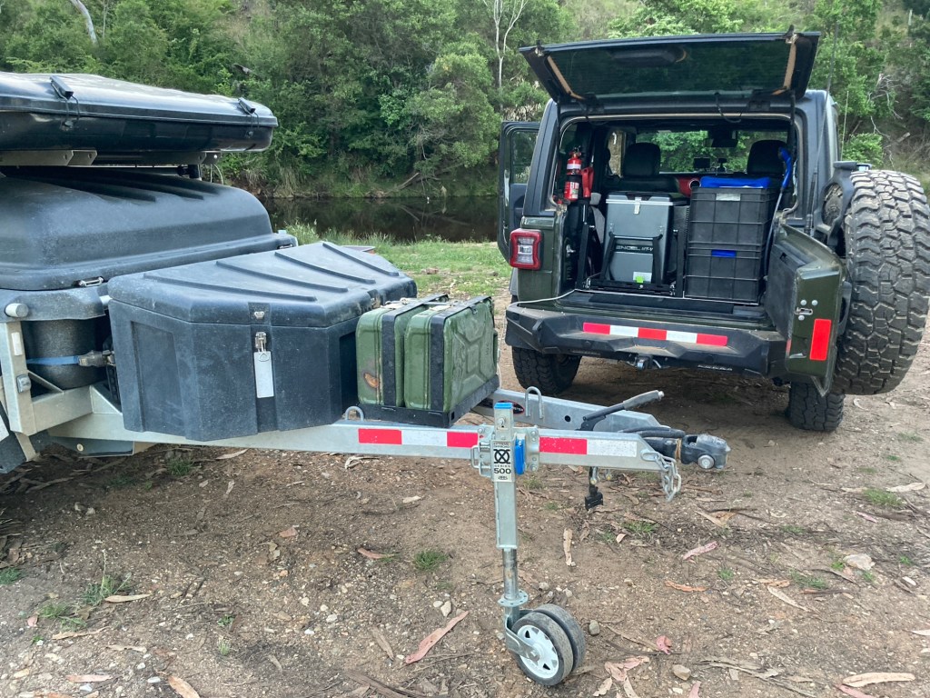
As my vehicle has a very small fuel tank (66l), and fitting an extra auxiliary tank is cost prohibitive and, at only 40l, practically useless, I am storing all my fuel on the Pod.
Initially just the two 20l jerrycans, a Stockman standard option, were not sufficient, so I fitted two additional jerrycans in a Frontrunner mounting on the drawbar.
2 additional jerrycans on drawbar.
This provides an extra 80l, making the total 146l, still too little for extended trips.
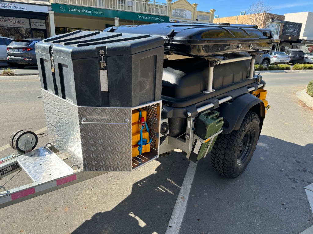
Recently I designed and commissioned a fuel bin, fitted under the tool box, which holds up to 8 jerrycans, making the total capacity 306l, including both Stockman and Frontrunner storage too.
I expect over 300l will be required to provide the 1,200km range (plus margin) required for some trips. Alternatively, when only a few extra jerrycans are required, the space can also be used to store recovery gear and camping essentials.
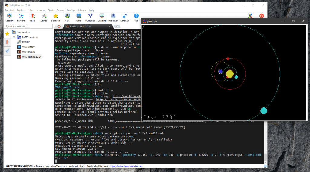
ReGIS graphics can be used to build high quality vector graphical output for embedded (Serial) devices, for example Arduino devices or retro-computers such as the RC2014 running CP/M, with the graphics output being displayed on a Windows 10 desktop. This method uses WSL Ubuntu with XTerm to support graphical output for Serial connected embedded devices, and a Windows based X Server to host the display.
Background
From the Wikipedia, ReGIS, short for Remote Graphic Instruction Set, is a vector graphics markup language developed by Digital Equipment Corporation (DEC) for later models of their famous VT series of computer terminals. ReGIS supports vector graphics consisting of lines, circular arcs, and similar shapes. VT series terminals supporting ReGIS generally allow graphics and text to be mixed on-screen, which makes construction of graphs and charts relatively easy.
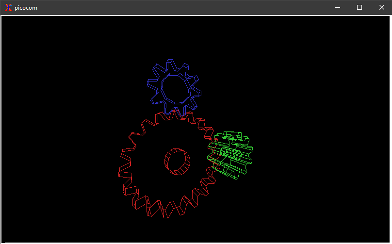
ReGIS is useful to display information that can be more easily interpreted as a diagram or a graph, such as plotting planet motion. It can also be used for vector graphics such as the GLX Gears program.
Today, where DEC VT series terminals are impractical to obtain, the easiest method to display ReGIS vector graphics is to use the XTerm terminal emulator. The XTerm fully supports ReGIS, but this capability is not enabled in general release versions. We’ll need to compile our own version with ReGIS enabled.
XTerm was developed for the X Windows System running on versions of Unix or Linux. So to use it on a Linux desktop machine running (e.g. Ubuntu) is quite straightforward. But if we want to use it on a Windows 10 desktop we will need to jump through some additional hoops and that is the point of this story.
The X window system (X) is a client / server windowing system developed in the mid 1980’s to support remote windowing. Unlike most earlier display protocols, X was specifically designed to be used over network connections rather than on an integral or attached display device. X features network transparency, which means an X client program running on a computer somewhere on a network can display its user interface (window) on an X Server running on some other computer on the network. The X Server is typically the provider of graphics resources and keyboard/mouse events to X clients, meaning that the X Server is usually running on the computer in front of a human user, while the X client applications run anywhere on the network and communicate with the user’s computer to request the rendering of graphics content and receive events from input devices including keyboards and mice.
To get XTerm to connect to a Serial interface, provided by an Arduino device or by a retro-computer such as a RC2014 CP/M machine, it is necessary to use a dumb terminal emulator to pipe the Serial bit-stream originating on the Serial-USB (FTDI) interface connection to XTerm without tampering with the non-displayable ESC code sequences that ReGIS uses for signalling. The best option is to use picocom for this role. Most other terminals “cook” the Serial to remove those ascii control characters that can’t be displayed, rather than passing them transparently.
We now have a complete solution to display ReGIS graphics originated on an Arduino or RC2014 on Unix / Linux machines. XTerm, configured with ReGIS enabled, together with picocom to pipe the Serial bit-stream is all that is required to display vector graphics on a Linux desktop.
To use Windows 10 as the desktop we will need to host a Unix / Linux machine running XTerm and picocom somewhere connected to the embedded device, and provide an X Server on the Windows 10 machine to display the window generated by XTerm. This can be done with a completely separate Linux machine, such as a Raspberry Pi or similar, but it is more convenient to do it using a Virtual Machine inside the Windows 10 platform provided by Windows Subsystem for Linux.
Microsoft provides two versions of the WSL. The first version WSL1 uses specific services and drivers to give Linux applications access to the Windows 10 kernel and file system. WSL1 supports access to Serial interfaces and the host file system. The use of the specific services and drivers between the Windows 10 kernel and Linux causes a performance penalty for most Linux applications, so WSL2 was introduced with a lightweight virtual machine, based on Hyper-V, to optimise Linux application performance. However WSL2 does not allow access to Serial interfaces or direct access to the Windows 10 file system. For most applications WSL2 is a better choice, but as we need to access the Serial interfaces directly we need to use WSL1.
With WSL1 installed, we can create an Ubuntu 22.04 LTS based Linux system to install and host our XTerm and picocom applications. And, optionally, we can build z88dk following these instructions, and install z88dk-libraries supporting ReGIS providing a C interface for RC2014 CP/M applications.
From our Windows 10 desktop machine we need to provide an X Server to enable XTerm to display its window on our desktop. There are several options available to do this. Xming (not free) and VcXsrv (open source) are two that are commonly recommended.
Another option to provide a Windows 10 X Server is MobaXterm. MobaXterm is proprietary, but is available for free for home users. It provides both an X Server (based on X.org) and secure shell (SSH) capability. SSH is particularly required where we need to connect to XTerm and picocom (the X client) running on separate Raspberry Pi hardware, but it is also useful for Windows 10 WSL. However, we can access WSL Ubuntu directly through its own terminal to initialize the XTerminal session, so for WSL Ubuntu the SSH capability is just a very convenient “nice-to-have”.
Implementation
Lets go through the steps required to get this all working…
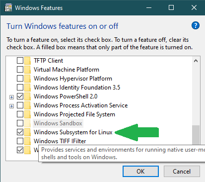
Windows Subsystem for Linux & Ubuntu
The Windows Subsystem for Linux (WSL) allows Linux / Unix distributions to use the Windows host computer. This instruction is based on Ubuntu 22.04 LTS, but other distributions will be similar.
Once WSL is installed then go to the Microsoft store and install Ubuntu 22.04 LTS. There are options for both Windows 10 and Windows 11, so choose the suitable alternative.
Ubuntu 22.04 LTS for WSL installed from the Windows Store.
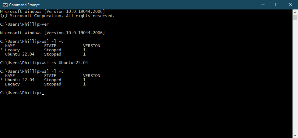
Confirm that you have both WSL1 and Ubuntu 22.04 LTS installed using. > wsl -l -v
And then set the default distribution to Ubuntu-22.04. > wsl -s Ubuntu-22.04
Setting the WSL version and Linux distribution.
Then launch the Ubuntu 22.04 LTS subsystem using the Windows Start menu command, to configure the new distribution. Update and upgrade the packages using apt, and make any other adjustments you need. Set up directories that you will use to build XTerm and (optionally) build z88dk. Building z88dk will ensure that you have the prerequisites to prepare .COM files for later uploading to your RC2014 CP/M.
At this stage DO NOT install XTerm or picocom from the Ubuntu repositories.
Launch the installer. It will automatically recognise your installed WSL and Ubuntu 22.04 LTS instances and will automatically configure SSH (local) terminal access for them. It will also allow you to connect directly to your Serial attached Arduino or RC2014 retro-computer if you configure a serial connection.
Use MobaXterm to connect to your Ubuntu 22.04 installation. The advantage of doing this is that the DISPLAY environment variable is automatically set, so that later XTerm can find the Windows 10 screen with no further setting needed. However, the direct Ubuntu 22.04 terminal can alternatively be used later for other purposes with no problem.
Preparing XTerm to support ReGIS
XTerm is the only known software solution supporting ReGIS. But it doesn’t support ReGIS in the default build. You’ll need to enable ReGIS support yourself by building and installing a customised version.
From your WSL Ubuntu command line use the below recipe. If you have not built any prior code on your WSL Ubuntu installation you may need to add additional packages, as signalled by the configuration step. Use apt to install them as needed.
> sudo apt install -y build-essential libxaw7-dev libncurses-dev libxft-dev
> wget https://invisible-island.net/datafiles/release/xterm.tar.gz
> tar xf xterm.tar.gz
> cd xterm-373
> ./configure --enable-regis-graphics
> make
> sudo make install
Install picocom for Ubuntu 18.04 LTS
From Release Version 3.0 picocom implemented advanced terminal control system calls, which are unsupported by the Windows 10 WSL1 implementation. This means that the Ubuntu 22.04 LTS supported release for picocom can’t be used with WSL1.
To work around this problem the Ubuntu 18.04 LTS Release Version 2.2 of picocom for amd64 can be installed. From your Ubuntu terminal, download the picocom 2.2-2 package and install it using dpkg.
Once it is installed, it is also useful to install the lrzsz package which provides XMODEM capability for picocom and other terminals.
It is also useful to hold the picocom package to ensure that it is not automatically upgraded to a later (unusable for our purpose) version. That is done with apt-mark.
To initialise XTerm for VT340 emulation, connecting to Windows 10 Serial device COMx, from the MobaXterm terminal use this command string. This command assumes we’re using 115200 baud 8n2 with RTS flow control, and we’re going to use XMODEM protocol to send binaries to our RC2014 or other device. Check the picocom manual to adjust the serial interface configuration to your own needs.
At this point a new XTerm window should appear on the Windows 10 desktop, supported by the MobaXterm X Server.
Assuming that you have a program which can generate ReGIS graphics already installed on your RC2014 (or Arduino), such as the demo program provided here, then it is time to start the program from the CP/M command prompt. Otherwise, it makes sense to use XTerm (with picocom) to access your RC2014 and upload the provided ReGIS demo program, or other any other program, using XMODEM protocol and the XM.COM or XMODEM.COM program on your CP/M installation, and then launch the program from the CP/M command prompt.
The resulting XTerm window (example image shown is planet-motion) should look similar to the image below.
Windows 10 with XTerm window displaying planet-motion.
And that is then all that needs to be done to enjoy high resolution vector graphics generated by a Serial connected embedded device such as an RC2014 running CP/M or an Arduino device.
The ReGIS library for z88dk has been developed to support ReGIS on the RC2014 and other Z80 CP/M machines. Therefore programs can easily generate the required Serial codes using the C functions provided.
The ReGIS library for Arduino is hardware agnostic, and supports all Arduino architectures. It can be installed from the Arduino Library Manager.
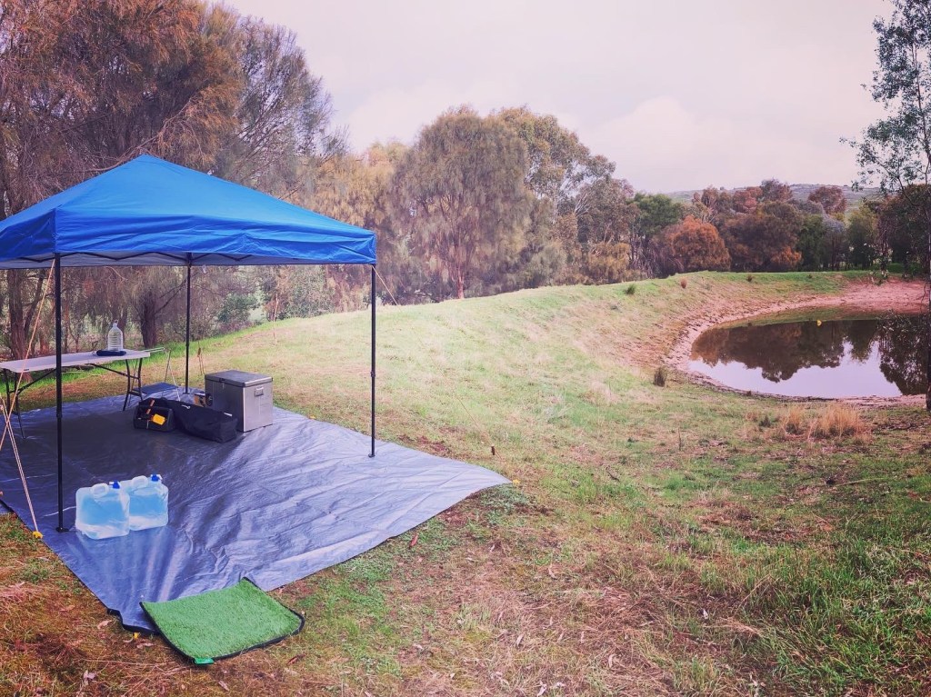
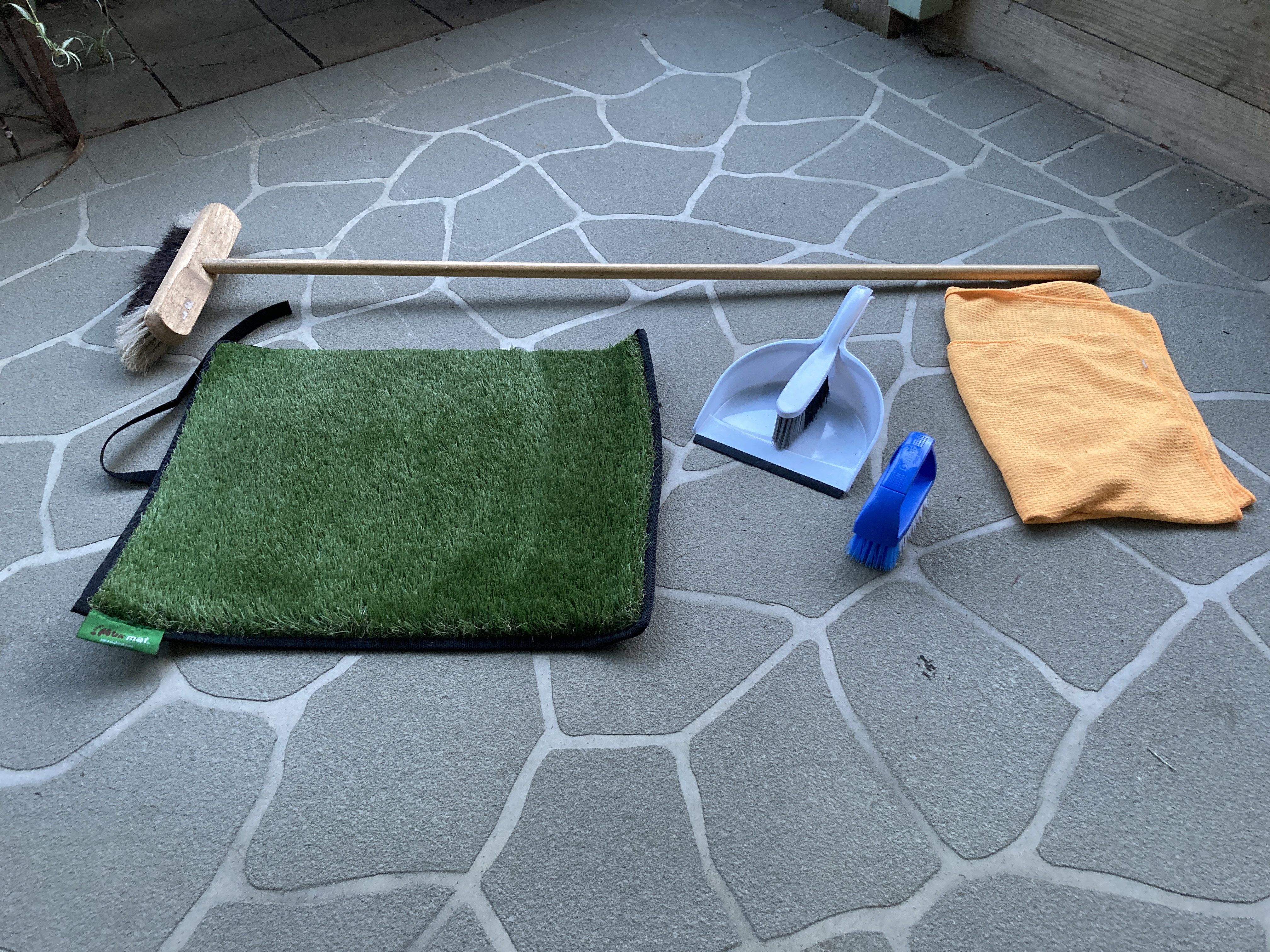
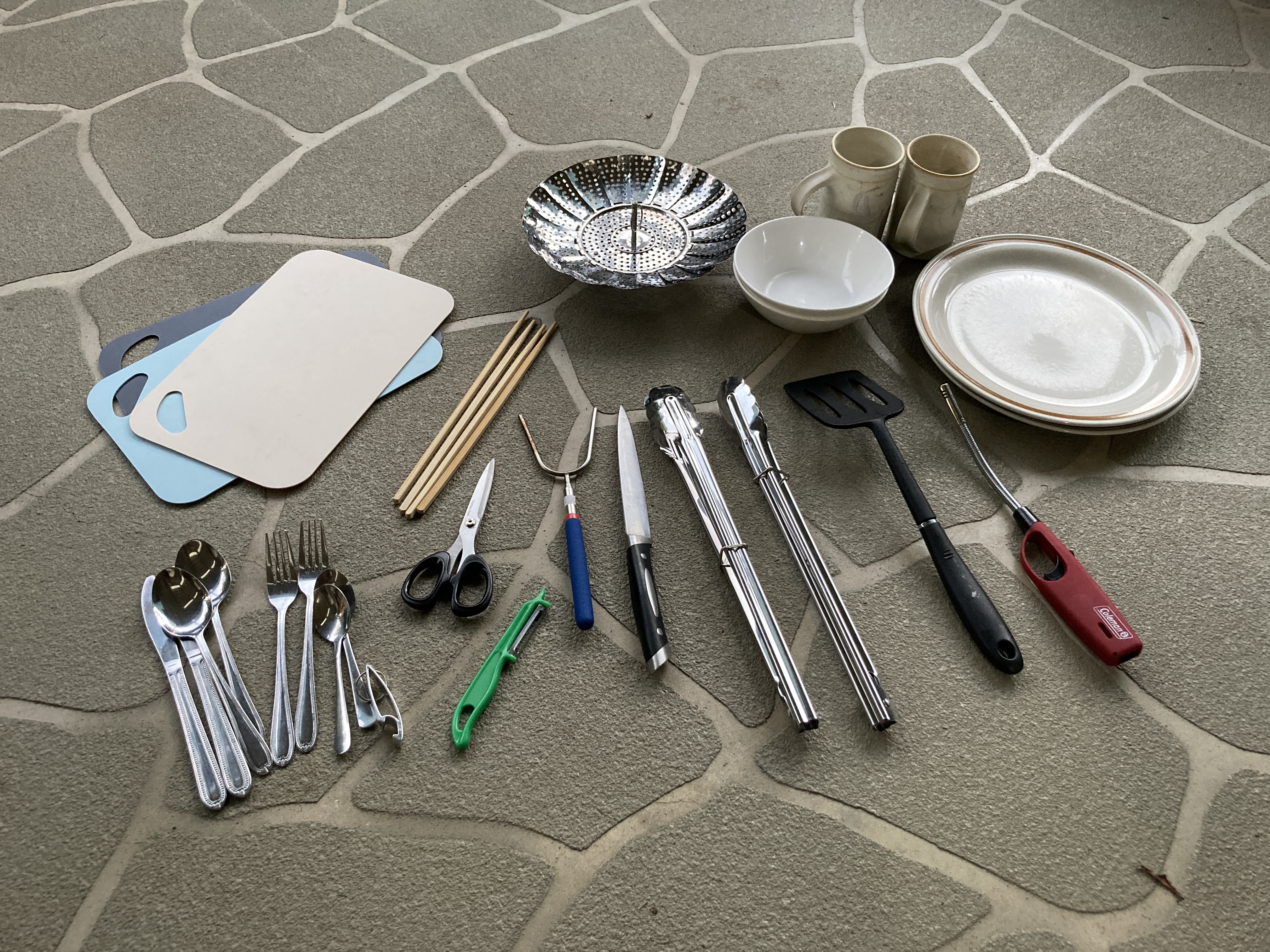
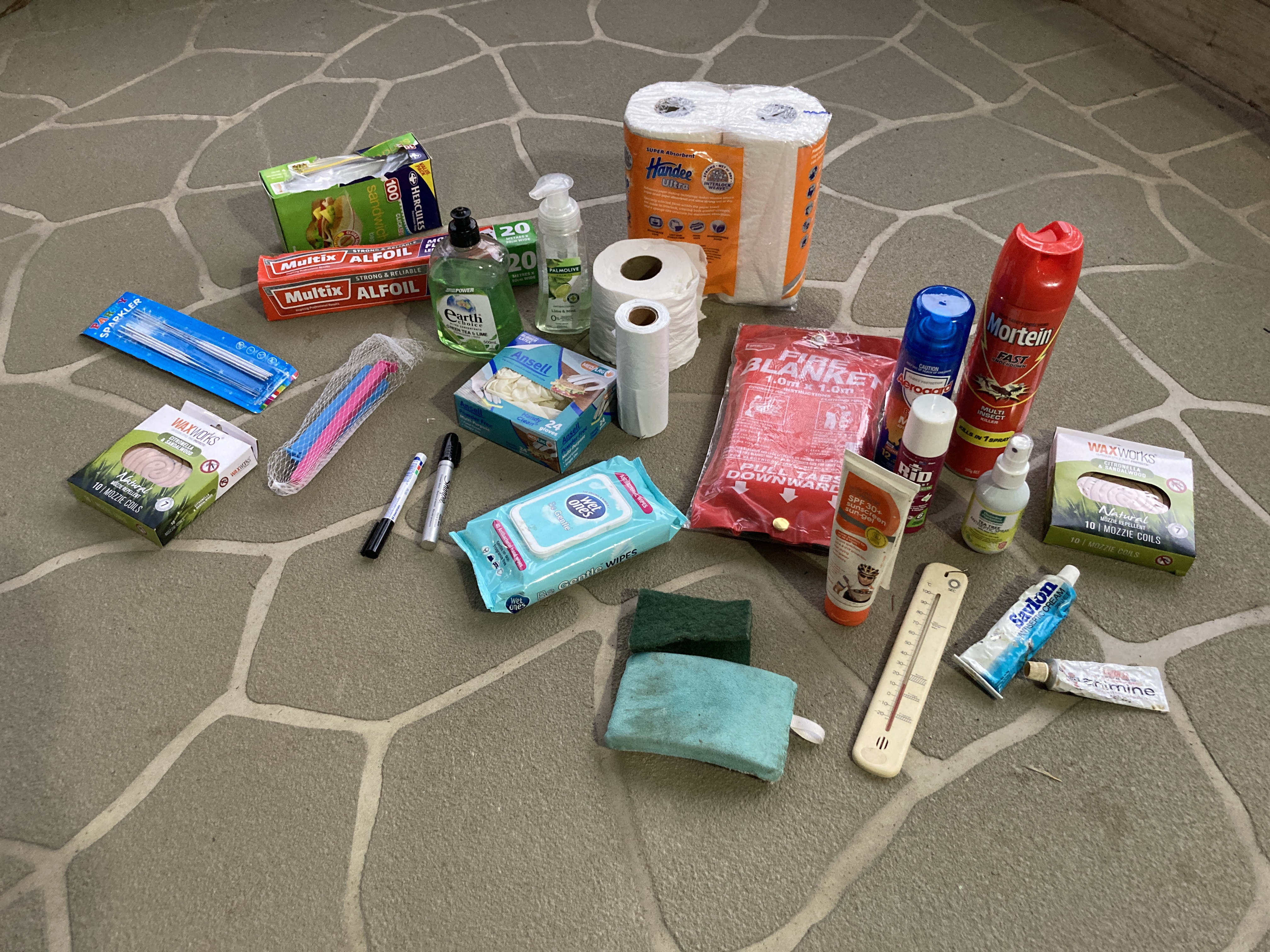
I’ve pitched a camp to test that I’ve got all the required things. The lists are great, but they don’t necessarily match completely with reality.
It is still a few months before my vehicle and pod trailer are going to be available, so my old station wagon is serving as the test mule. I loaded everything in and transported it to the camp. It took two trips as I’m minding an extra dog, and have to allow space to transport dogs rather than equipment.
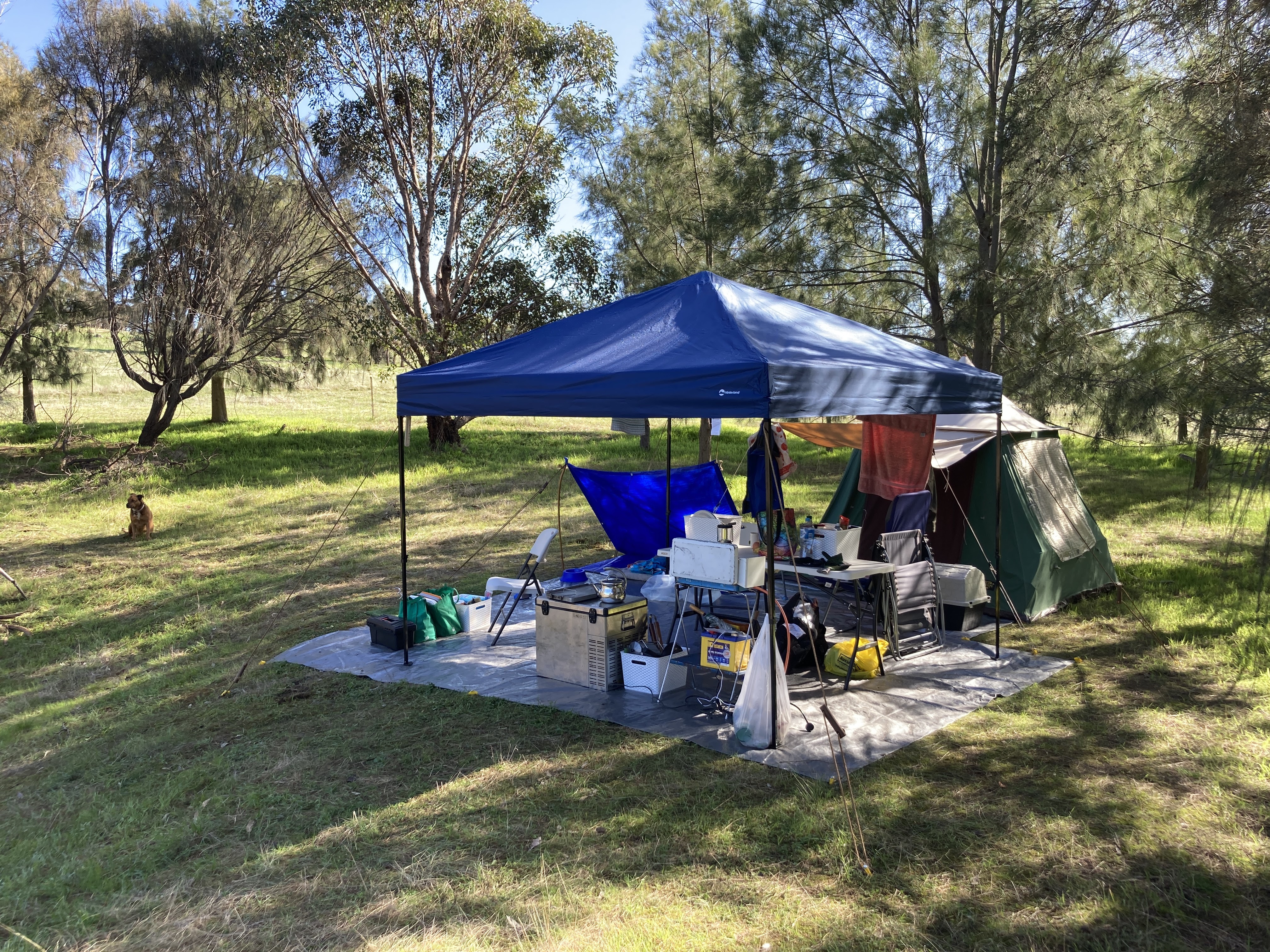
Of course the weather doesn’t play nice, and it is raining continuously as I try to set up the camp. And, since I’ve pitched camp about 80m from the closest approach, everything has to be carried in through the rain.
Pitching camp in the rain.
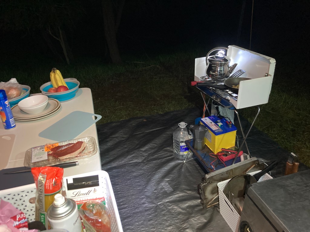
The first job is to work out where the table, and cooker work best. I’ve decided to put the table into the middle of the gazebo space, and then use one side for cooking, and later the other side for sitting / reading / writing. Putting the kitchen in the far corner allows me to empty water, coffee dregs, etc onto the grass, and keeps the inescapable ants away from the tent.
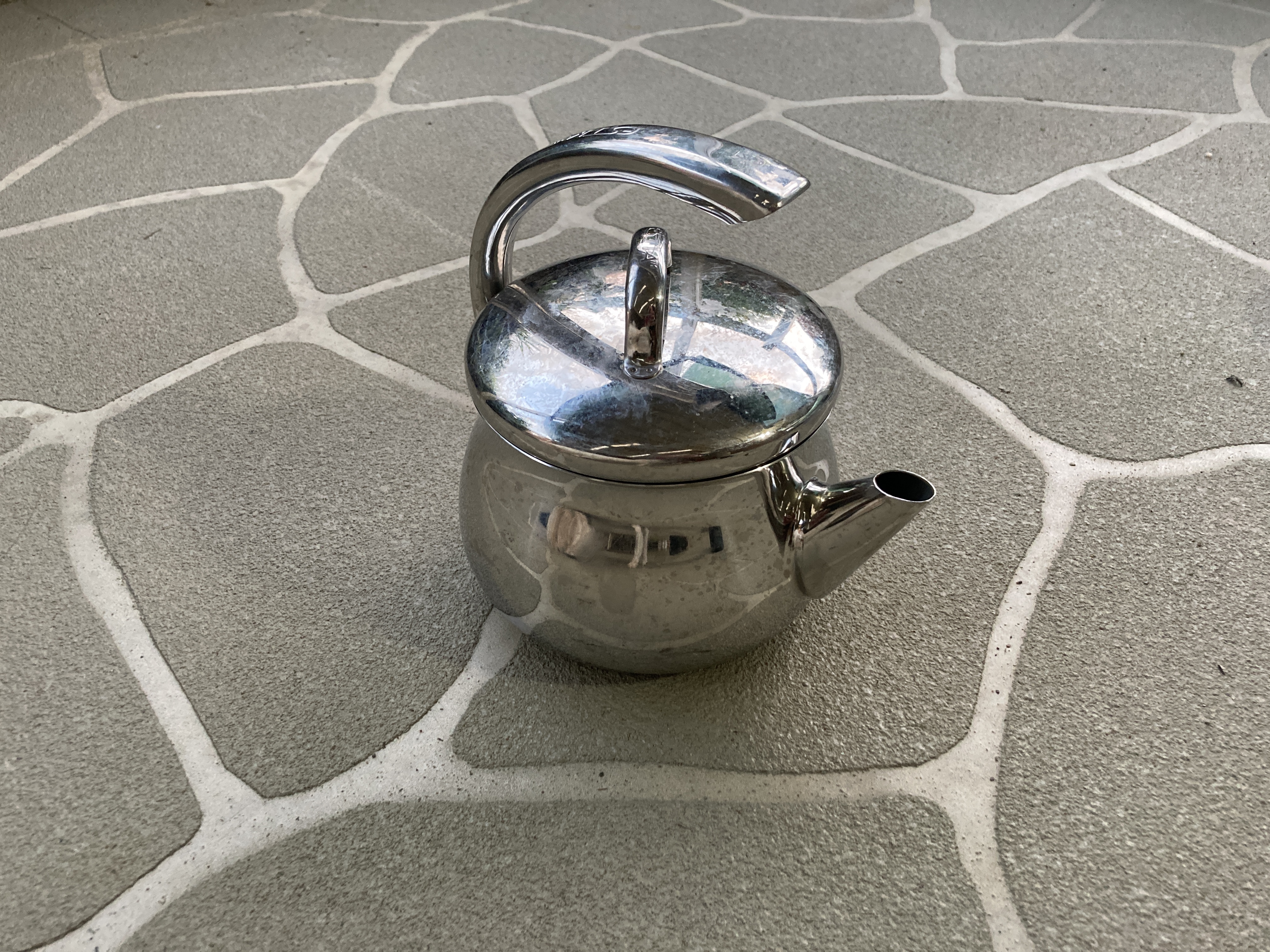
Very happy with the old Primus stove. I’ve inherited many pieces of my kit, including the tent, cooker, and quite a few tools and whatnot. So it is the first time that the 1970’s stove has been used in a long while.
Kitchen in the rain.
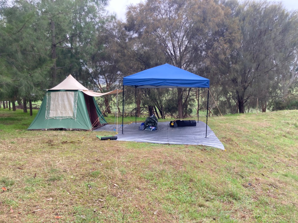
Similarly, my Terka Tent from Czechoslovakia also looks to be performing well. It hasn’t been out of the bag since the early 1980s. Yet, after standing in the rain all day, it still looks to be fine inside. But time will tell.
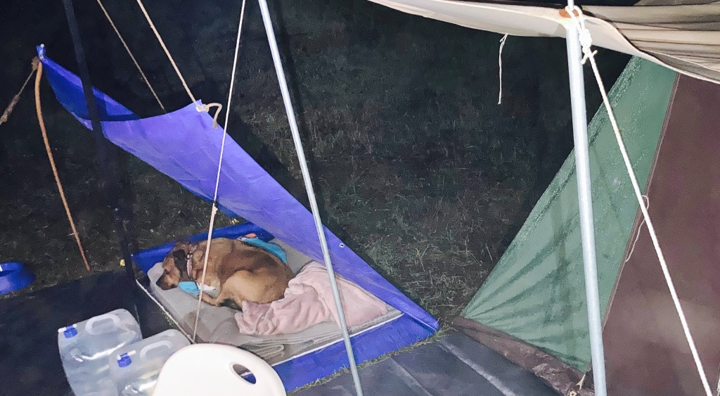
As I’m minding an extra dog I had to build a bivouac for her. Using a cheap tarp found in the local supermarket pegged out with 1/3 under and 2/3 over, a piece of 10mm insulation board to get her off the ground, and her own blankets from home, I was able to make her a dry and warm place to sleep.
Dog camping in style
General Impressions
I’d forgotten how slow it is to get things done. In a house there’s hot water on tap, and boiling water from an electric kettle, and food straight out of the refrigerator. Living in the outdoors, things are not so time efficient. To make a coffee requires preparation, and cleaning up. A choice has to be made as to whether to clean up first, and have cold coffee, or to enjoy the coffee, but then have the chore of cleaning up after the relaxation of consuming the coffee. Similarly, preparing toast, making tea, or any other process around the kitchen needs extra steps that either add time, or reduce the “enjoyment” value of the activity.
Over the weekend the weather got better and better, and once things had dried out the ease of doing everything increases. Fortunately, as it wasn’t too windy, the gazebo provides 9m2 of living space protected from the rain. So, it seems that at least in still weather the gazebo is a valid alternative to a vehicle awning.
Proving to myself that there is no real benefit to a vehicle awning is a big thing. Vehicle awnings are expensive, are heavy high on the vehicle, and they increase fuel consumption because they rely on having a roof rack to mount them. They also force you to limpet yourself to the side of your muddy or dusty vehicle and they need to be closed before the vehicle can be moved.
I used some extra guy ropes looped through the gazebo frame and anchored to the ground, to hold it very stable. The gazebo roof is only held onto the frame with Velcro. Should a strong wind gust take the nylon roof off, the frame will remain tied down. A piece of nylon material floating or flapping about won’t do any damage, and will probably come back down to earth quickly as it has no form holding the wind. Alternatively, attempting to hold a 9m2 “sail” to the ground in the face of a strong wind gust is a pointless endeavour.
Camp on Day 3
I am pretty happy with the kitchen set up. The stove, and substitute Engel refrigerator are easy to use, and effective. I purchased some wicker (plastic) boxes, which I used to store 1. Food, 2. Crockery, 3. Pans and Utensils, and 4. Cleaning and Utility products. These are much easier to use than plastic shopping bags (which would have been the temporary alternative), yet they’re not perfect. The issue is juggling them from the ground (in the rain), to the 5’ Lifetime Table or the top of the Engel. If I build a kitchen storage in the back of the Rubicon, then that may solve the juggling of containers, but it may create an issue where things are hard to access. Another alternative is to organise the boxes by process or task or by frequency of access, rather than by topic as I’ve done now.
The Night
For the sleeping arrangements, I’ve got it generally right, but I’m still not totally happy. The combination of the stretcher and mattress makes for a very warm and comfortable bed. However, the way I’ve organised the YHA Bedsheet together with antique woollen blankets is uncomfortable. They slip around on the mattress, and become tangled quite easily. One very pleasing accident with the YHA Bedsheet is that the pillow slip serves to hold the pillow from slipping off the end of the bed. As the stretcher has no “head” this can happen easily, so it is very useful that the pillow is retained by the sheets.
As I’ve prepared the bedding into a rolled swag, with an 6’x8’ tarpaulin outside the self-inflating mattress, sheets, and blankets, the idea of storing everything together has worked well. The plan is that having all the bedding rolled together will allow the bed to be dropped anywhere and used, and stay dry until unrolled even if it is carried in the rain.
Useful Things
Because the Engel refrigerator is very heavy, as an exception I used a handcart to move it from the vehicle to the camp site. And, because I had it with me I was also able to use it to move the 12V battery, 20l water containers, and other heavy items. A handcart is not something that I’d previously considered taking along, but now I think if there’s space then it will come with me. It will be useful for moving water, firewood, and many other backbreaking tasks.
I didn’t bring a broom. I should have. A hand brush is useful to sweep standing water, meat ants, and leaves off the ground tarpaulin, and to clean the tent and generally around the site. But I think that a broom would work better and be much easier on the back.
I’ve taken some pictures of the things that worked, to remind me what comes with me.
Stadium Seats for chairs are very comfortable, and weigh nothing. They can be used anywhere. The handcart is a very useful addition. Not sure about collapsing water containers. Sure they’re easy to store and keep handy, but they’re not easy to use when half full. So, it is best to transfer their contents into a “working” container. The kettle was used more often than any other utensil. Hot water is essential.
And finally, the Australian bush just loves to come home with you. This “little” guy was hitching a ride in the cutlery container. He joined with the meat ants roaming around the campsite, and mosquitos swarming everywhere, making this camp a 3 of 6 wildlife expedition. Fortunately no scorpions, or snakes. And no centipedes.