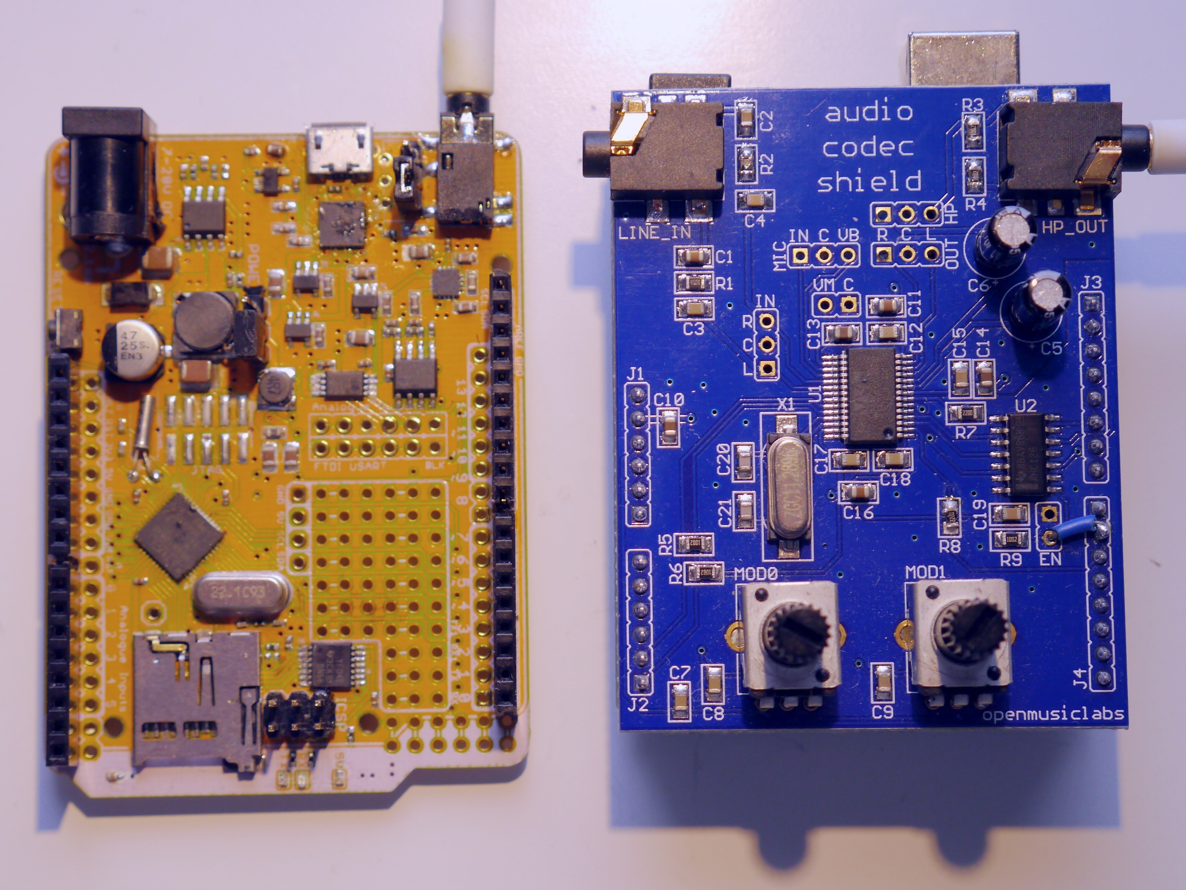
For the past year, I’ve been prototyping an Arduino clone, the Goldilocks Analogue, which incorporates advanced analogue output capabilities into the design of the original Goldilocks with ATmega1284p AVR MCU and uSD card cage. Recently the design scope crept up to include two SPI memory devices (EEPROM, SRAM, FRAM), and microphone audio input. But, before I go through another prototype cycle, I thought it would be a good idea to build some demonstration applications, showcasing the capabilities of an arduino R3 compatible platform with integrated analogue output and have some fun with audio.

Some of the initial tests I’ve built include some 8 bit algorithmic music and, using two Goldilocks Analogue prototype devices, a digital walkie talkie using Xbee radios. They were fun, but don’t really demonstrate the full range of the audio capabilities of the platform.
It seemed appropriate to build a synthesizer using the Goldilocks Analogue as the platform, and a Gameduino 2 shield incorporating a FDTI FT800 EVE GPU, and see how close I could get to a musical outcome.
Research
Before randomly building something that made a bunch of squeaky sounds, I thought the best thing to do is to learn something about the field of analogue synthesizers and synthesizing audio.
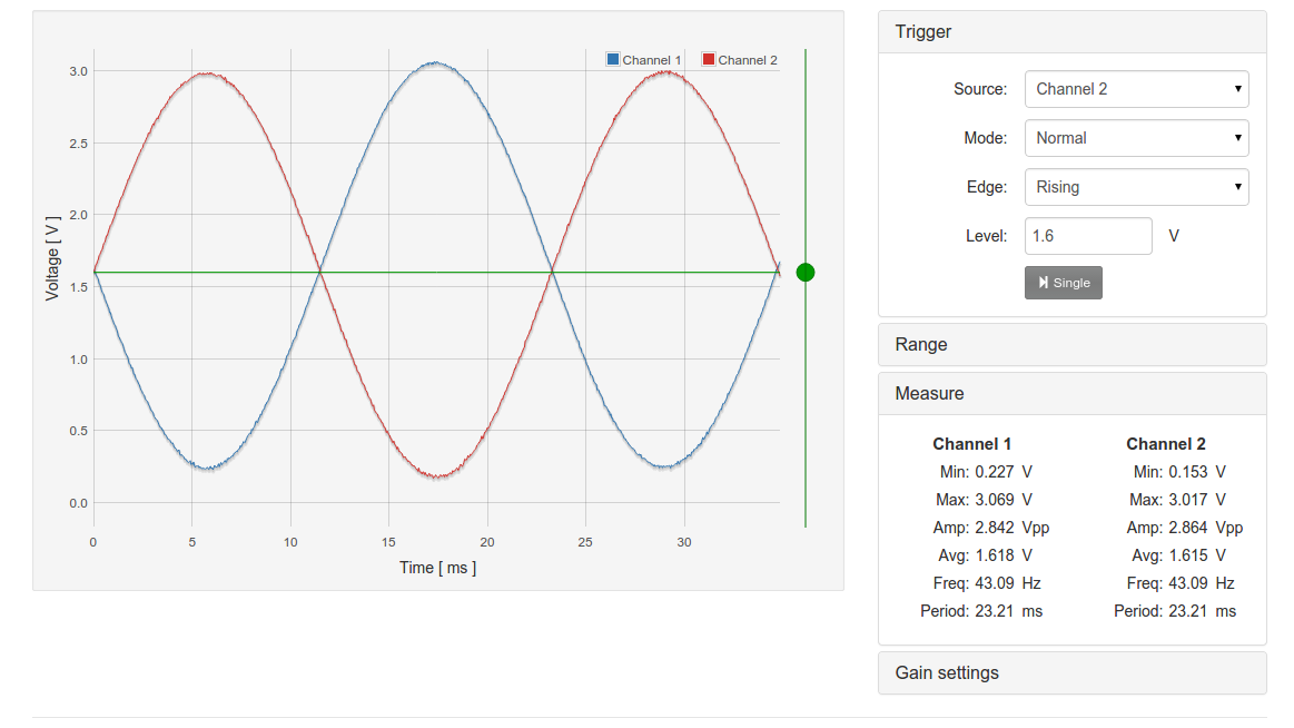
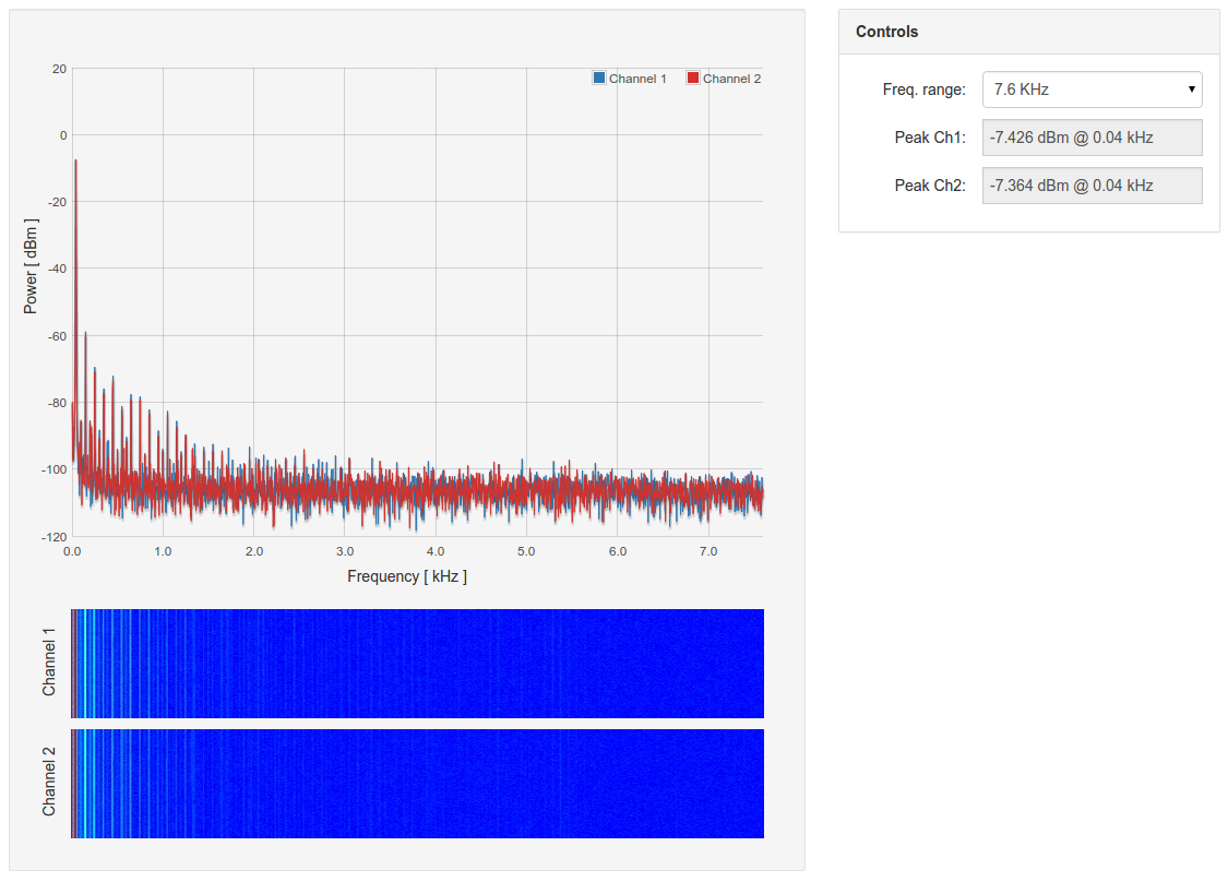
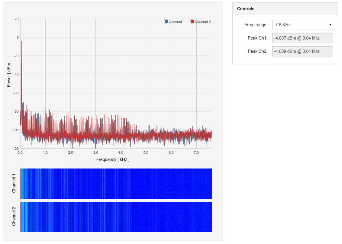
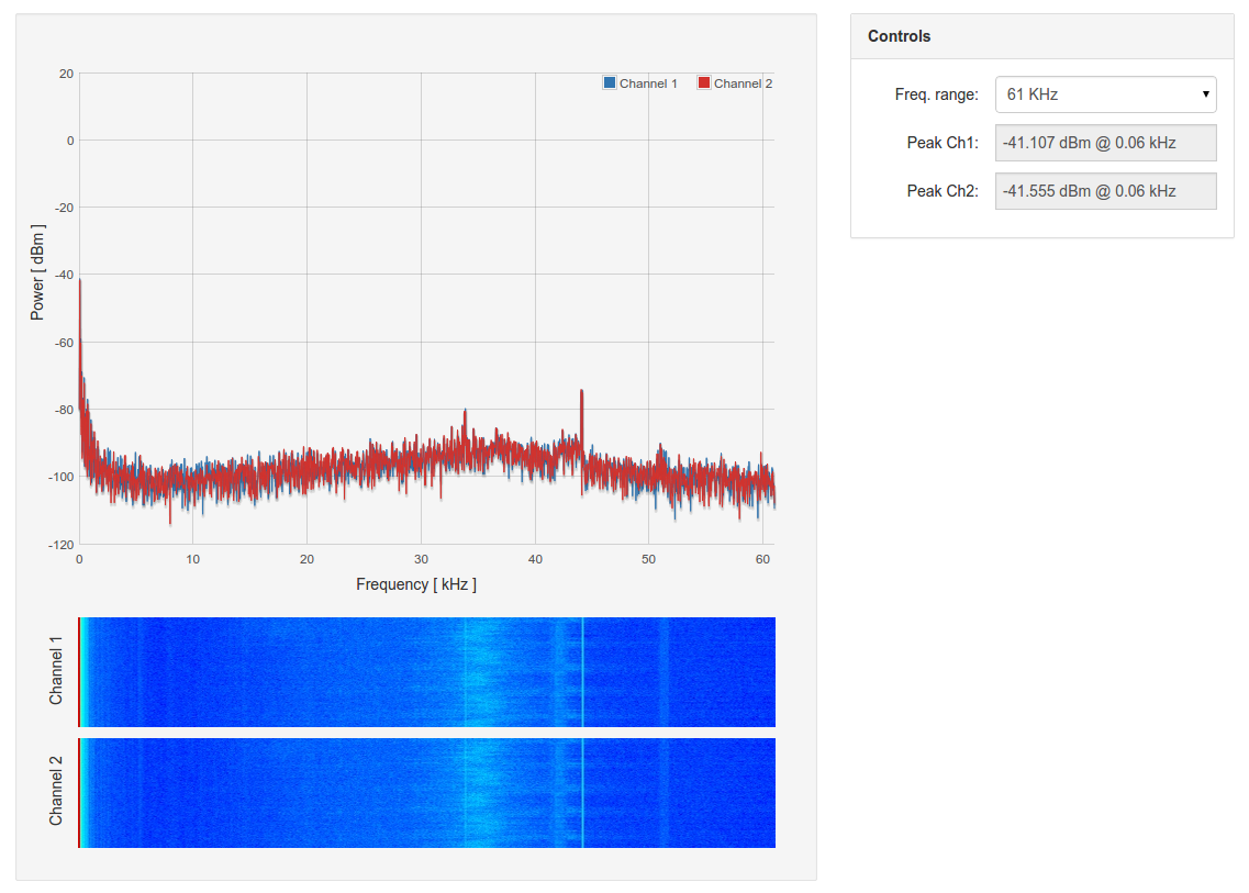
I also obtained some simple analogue synthesizers from Korg to see exactly what they produce, so I could copy them. Some people write that this monotron analogue synthesizer family are good examples of a low cost musical instrument. I found it very interesting to examine the wave forms produced by the various settings.
-

- Chained Korg monotron synths
-
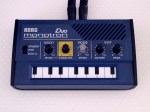
- Korg monotron DUO
-
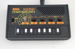
- Korg monotron DELAY
Using the features of the two Korg devices, I was able to define the goal for the synthesizer that I wanted to build using the Goldilocks Analogue.
The Korg monotron DUO has two voltage controlled oscillators (VCO1 and VCO2), which produce square waves. The VCO1 has a pitch setting, which defines the basic frequency at which the ribbon keyboard operates. The ribbon keyboard can be set to have a major scale, a minor scale, a full chromatic scale, or be a ribbon with no set notes. For clarity, the pitch on the DUO is analogue, so there is no guarantee that the notes generated by the ribbon keyboard will be in tune.
The VCO2 pitch can be modified either below or above the pitch of the VCO1. In its middle section, with some care, it can be matched exactly to the VCO1 setting. The switch allows either just the VCO1 or both VCO1 and VCO2 to produce sound. A separate XMOD intensity knob allows the VCO2 to modulate the frequency of the VCO1 oscillator, producing cross-modulation.
The monotron DUO contains the famous Korg MS-20 resonant low pass filter, which can be adjusted for both cut-off frequency and intensity of the resonant frequency. Setting the filter values allows the square wave noise generated by the two oscillators to be shaped into very interesting tones.
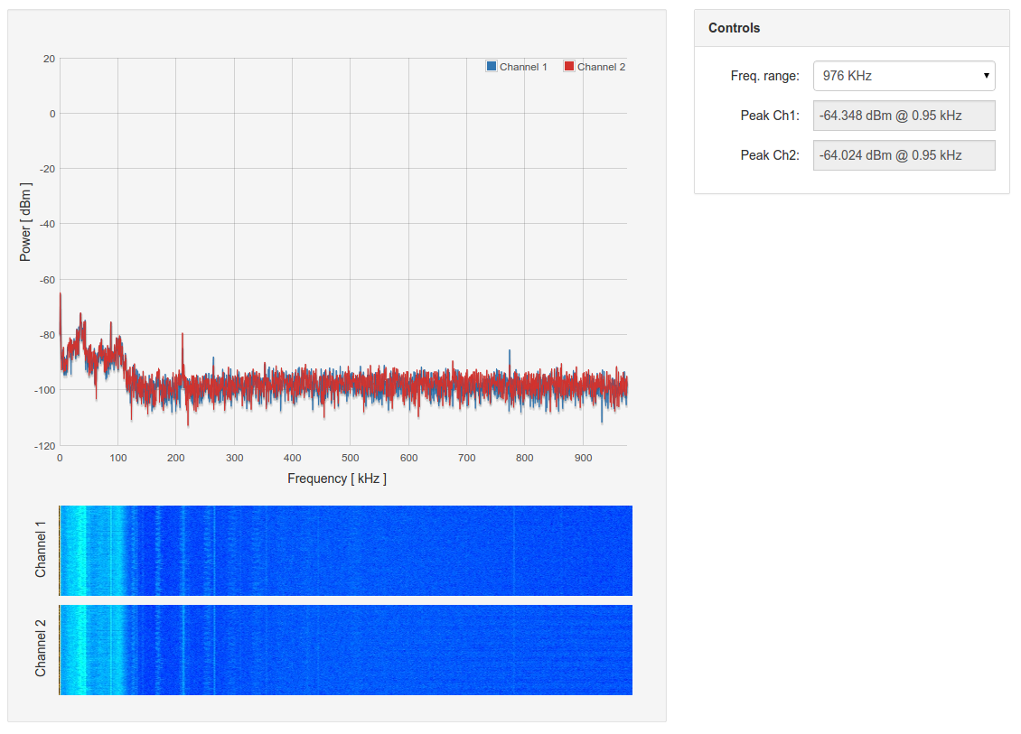
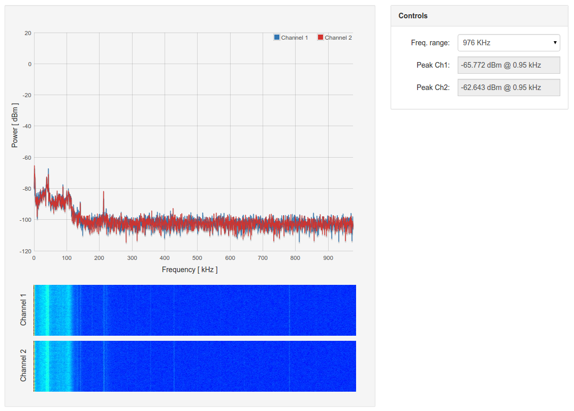
The Korg monotron DELAY is a very different device from the DUO. It has two oscillators, but only one at audio frequencies. The audio oscillator produces a saw-tooth wave at a frequency controlled by the ribbon keyboard. On the monotron DELAY there is no capability for playing specific notes as the keyboard is only available in ribbon mode. The second oscillator of the monotron DELAY is a low frequency oscillator (LFO), which can be adjusted from 1Hz up to about 30Hz. This LFO can produce either a triangle wave or a square wave to modulate the main audio oscillator. This is used mainly to apply vibrato to musical tones, or to produce very unusual tone ramps. The intensity and pitch of the LFO are controlled by knobs.
The Korg low pass filter present in the monotron DELAY is only adjustable for its cutoff frequency, so it is less flexible and interesting than the monotron DUO implementation.
The monotron DELAY is really built to showcase the analogue space delay functionality, which can be adjusted in both length of delay, and in intensity of feedback. With about 1 second of delay and 100% or more feedback possible, very short sequences of notes can be played and then built upon.
I’m not particularly musical, but I spent some very pleasant hours playing with the two Korg synthesizers experimenting with the sounds available from their very simple platforms, and used their capabilities to guide me in what to build into my Goldilocks Analogue synthesizer.
The next piece of research was to understand how to generate analogue wave forms using direct digital synthesis, and then how to modify sound of the wave forms using convolution or modulation in the time domain.
Design Specification
Having the two Korg devices as an inspiration, and reading about the original Moog synthesizer capabilities from the 1970’s, made the specification pretty straight forward.

The Goldilocks Analogue synthesizer has three oscillators, two of which operate at audio frequencies, being VCO1 and VCO2, and one low frequency oscillator, being LFO. The VCO1 is tuned in octaves at correct concert pitch, so that notes played would be at the right frequency. The VCO2 is pitched relative to the VCO1 pitch, and would range minus one octave to plus one octave (or half the VCO1 frequency to double the VCO1 frequency). The LFO is adjustable over the range from 1 Hz to 40 Hz.
I had decided to let each oscillator take one of two wave forms. For VCO1 I initially chose square wave, and saw tooth wave, to be able to replicate the exact sound of the Korg devices. I’ve since decided to move the saw tooth wave to the VCO2, and replaced it with a sine wave on VCO1. It is good to have the pure tone at the correct frequency for tuning instruments. An A4 from the Goldilocks Analogue Synthesizer will, for example, always be 440Hz.
For VCO2 I selected a triangle wave and a saw tooth wave. And, for the LFO there is a sine wave and a triangle wave available. I should point out that changing the wave form available to each oscillator is no more complicated that replacing the look-up table associated with the setting, and there is space available in the ATmega1284p to store at least another 4 separate wave form tables in flash memory, even without extending to on-board SPI EEPROM, or uSD storage.
In the mixing section the intensity or volume of each of VCO1 and VCO2 can be set. It is possible to turn off either oscillator. The intensity of the LFO effect is controlled too. The LFO modulates both the VCO1 and the VCO2. The final input is the cross modulation of VCO1 by the VCO2. Very interesting tonality is created by modulating VCO1 by pitches very close to its own frequency.
Each note is put through an exponential Attack and Release envelope, to give the note some shape. The mixed signal is then be sent to the voltage controlled filter. Using the current set up, the sample rate is 16,000 samples/second, which is enough to produce 6 octaves. The upper two octaves remain implemented, but are not reconstructed accurately. I have implemented a Biquad IIR filter to enable the output to be high, low, or band pass filtered. The default set up is for low pass filtering. The filter -3dB frequency, and the ringing levels can be adjusted for different musical effect.
Following the filter stage, the signal enters the space delay stage. The space delay stage can have only about half a second of delay, because of the RAM limitations (16kByte) of the ATmega1284p. So up to 6700 16 bit samples are supported by the space delay function. Samples are recovered from the delay buffer, and mixed with the new signals, then injected back into the delay loop. This creates an infinite loop of samples, depending on the amount of feedback set by the FEEDBACK control.
The final signal output level is controlled by a MASTER volume control. Additionally, an EEPROM STO and RCL capability for the settings has been implemented. Only the most recent settings are stored, which can be recalled when power is restored.
As the keyboard notes are generated using a look up table, multiple keyboard tuning options are possible. I have implemented Concert Tuning (A4 = 440Hz) and Equal Temperament (commonly used for pianos), and Verdi or Stradivari tuning (C4 = 256Hz) with Just Intonation Equal Fifths as an alternative. There is a toggle to chose between either these two options. Any tuning can be generated, and then loaded as the note table.
GUI Implementation
The GUI of the solution depends on a Gameduino 2 screen, which is based on the FTDI Chip FT800 EVE GPU device. The FT800 was the first EVE GPU available from FTDI and it can only support single touch. This limitation makes it only partially useful as a product to support this application. The most interesting sounds are generated by bending the controls whilst playing the notes. Fortunately there are newer EVE GPU devices that support multi-touch and they would make a better platform if this synthesizer were to become more than just a demonstration.
The GUI makes extensive use of FT800 co-processor widget capabilities being dials, toggles, keys, and text. Some examples below.
// text
FT_GPU_CoCmd_Text_P(phost, 300,  8, 27, OPT_CENTER, PSTR("VCF"));
FT_GPU_CoCmd_Text_P(phost, 300, 25, 26, OPT_CENTER, PSTR("CUTOFF"));
FT_GPU_CoCmd_Text_P(phost, 300, 95, 26, OPT_CENTER, PSTR("PEAK"));

// toggles
FT_API_Write_CoCmd(TAG(LFO_WAVE));
FT_GPU_CoCmd_Toggle_P(phost, 13,242,46,18, OPT_3D, synth.lfo.wave, PSTR("SIN" "\xFF" "TRI"));

FT_API_Write_CoCmd(TAG(KBD_TOGGLE));
FT_GPU_CoCmd_Toggle_P(phost, 405,130,60,26, OPT_3D, synth.kbd_toggle, PSTR("CONCRT" "\xFF" "VERDI"));

// dials
FT_API_Write_CoCmd(TAG(DELAY_FEEDBACK));
FT_GPU_CoCmd_Dial(phost, 365,125,20, OPT_3D, synth.delay_feedback); // DELAY FEEDBACK

FT_API_Write_CoCmd(TAG(MASTER));
FT_GPU_CoCmd_Dial(phost, 440,55,26, OPT_3D, synth.master); // MASTER
The integrated touch tracking capability makes it very easy to parse touch into specific commands.
readTag = FT_GPU_HAL_Rd8(phost, REG_TOUCH_TAG);

if (readTag > 0x80)// tag is greater than 0x80 and therefore is a dial.
{
	TrackRegisterVal.u32 = FT_GPU_HAL_Rd32(phost, REG_TRACKER);

	switch (TrackRegisterVal.touch.tag)
	{
	case (VCO1_PITCH):
		synth.vco1.pitch = TrackRegisterVal.touch.value & 0xe000;
		break;
	// continues...
	}
This integrated touch tracking capability can return which dial (slider / scroll bar) has been touched, and the relative position of the touch. This same position value can then be used in the display command to set the position of the dial (slider / scroll bar), providing direct feedback on the GUI.
The main GUI task simply calls the touch function, and if there is a touch recorded the GUI is updated, and the revised settings entered into the analogue audio control structure. Otherwise if there are no touches recorded there are no processor cycles wasted updating the display. The FT800 EVE GPU continues to display the same content until a new display list is loaded into the GPU memory.
When a keyboard touch is recorded, the tone generation information is updated, and this then directly impacts the output tone generated by the audio section.
//  setting the phase increment for VCO1 is frequency * LUT size / sample rate.
//  << 1 in SAMPLE_RATE is residual scale to create 24.8 fixed point number.
// The LUT is already pre-scaled << 7 in the calculation.
// The LUT can't be pre-scaled to << 8 because this creates numbers too large for uint32_t to hold,
// and we want to allow the option to vary the SAMPLE_RATE at compilation time, so it has to stay in the calculation.
synth.vco1.phase_increment = (uint32_t)pgm_read_dword(synth.note_table_ptr + stop * NOTES + note) / (SAMPLE_RATE >> 1);

// set the VCO2 phase increment to be -1 octave to +1 octave from VCO1, with centre dial frequency identical.
if (synth.vco2.pitch & 0x8000) // upper half dial
	synth.vco2.phase_increment = ((synth.vco1.phase_increment >> 4) * synth.vco2.pitch ) >> 11;
else // lower half dial
	synth.vco2.phase_increment = (synth.vco1.phase_increment >> 1) + (((synth.vco1.phase_increment >> 4) * synth.vco2.pitch) >> 12);

// set the LFO phase increment to be from 0 Hz to 32 Hz.
synth.lfo.phase_increment = ((uint32_t)synth.lfo.pitch * LUT_SIZE / ((uint32_t)SAMPLE_RATE << 4) );
The phase increment desired, respective to the relevant tone desired, is read from a look up table containing 8 octaves each of 12 notes for VCO1. VCO2 phase increment is then set as a proportion of VCO1. And LFO phase increment is set to range from 0 to around 30 Hz. With this information, and the selected wave form look up table, the audio implementation can do its thing.
Audio Implementation
The synthesizer audio section is implemented in one function, that is executed each time a new sample is generated. This means at 12,000 samples/ second sample generation frequency, we have 83 micro seconds to generate the final sample to be pushed to the Goldilocks Analogue MCP4822 12 bit dual channel DAC.
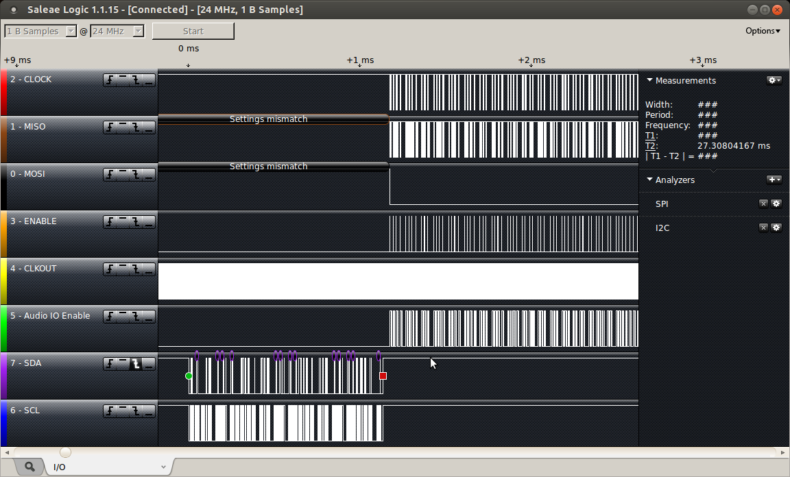
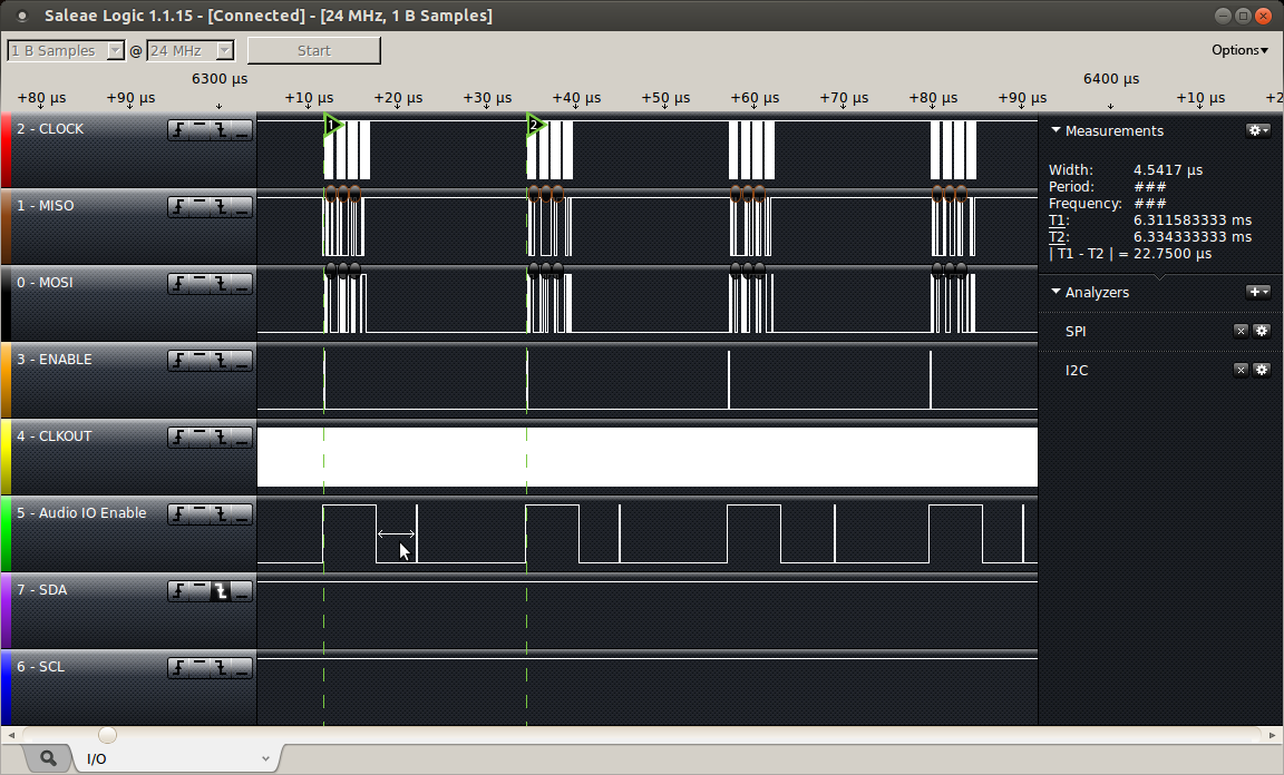
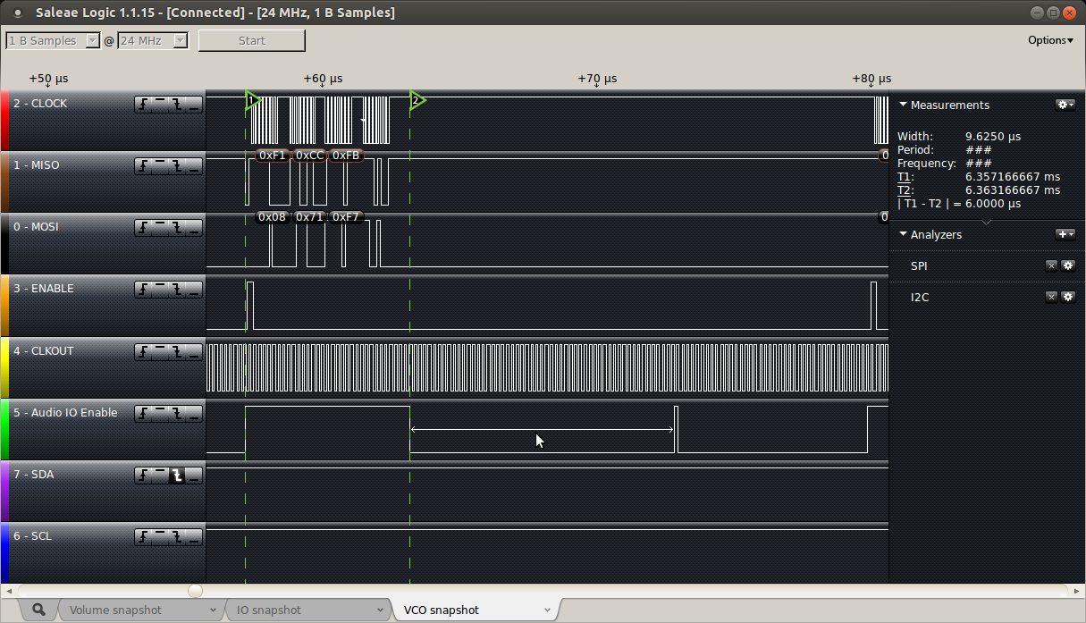
The current sample generation routine takes under 45 micro seconds to complete with 3 Oscillators running, so there is a little head room still available. With some further coding improvements it was possible to raise the sample frequency to 16,000 samples/sec as the sample generation frequency. The below logic trace shows the main SPI interface (SCK, MISO, MOSI, _SS) delivering commands to the EVE GPU, and the lower MSPI interface (MSPI SCK, MSPI MOSI, MSPI PING) providing the calculated samples, every 83 micro seconds, to the DAC.
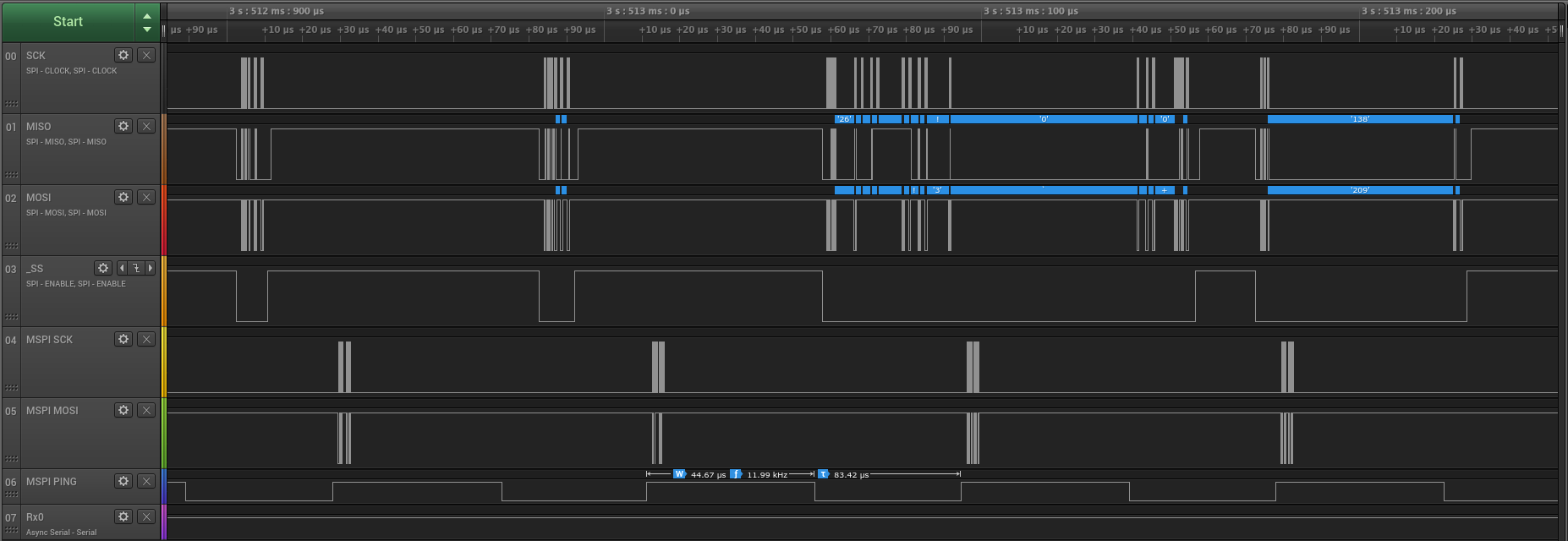
Goldilocks Analogue Synthesizer, with 3 Oscillators operating.
It is clear to see that two EVE GPU transactions are being interrupted by the DAC output, but because the main SPI interface is not changing state the transaction is faultlessly resumed once the DAC interrupt is completed.
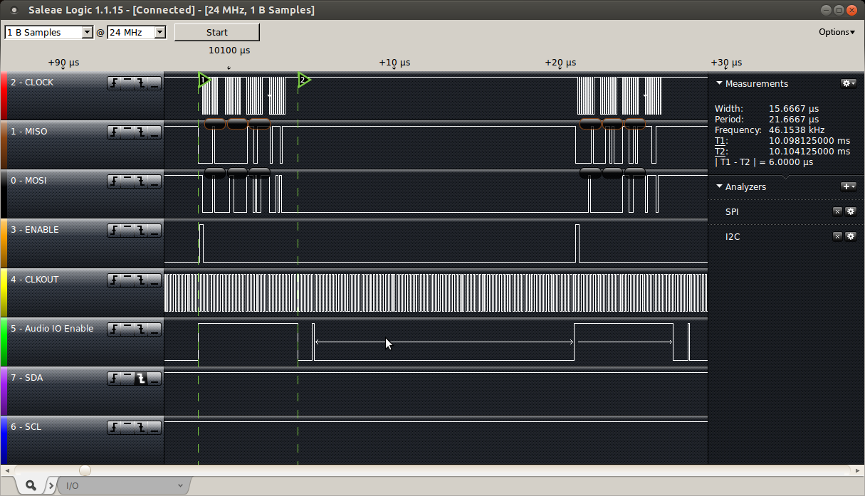
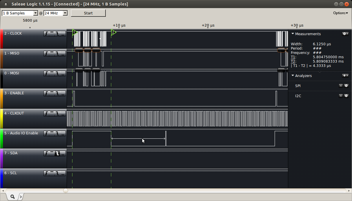
In contrast, when there are no oscillators running because no key is pressed, the sample generation routine takes just 28 micro seconds to complete. The logic trace below shows the change of state from 0 to 3 oscillators.
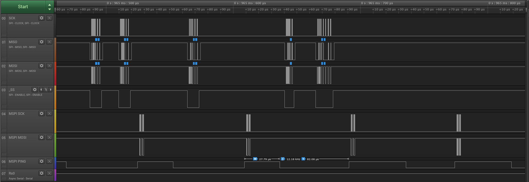
Goldilocks Analogue, with no Oscillators operating.
There is little time available to calculate sample values in real time, so all of the samples are pre-calculated and are stored in look-up tables (LUT). Each LUT contains 4096 16 bit samples, which gives 12 significant bits of accuracy for the values. I chose 4096 samples because the ATmega1284p has sufficient storage to support multiple tables of this size in its flash memory. Smaller LUTs would sacrifice accuracy, and larger LUTs would compromise on the number of available wave forms.
I have prepared LUTs for sine wave, square wave, triangle wave, and saw tooth wave options. Another advantage of the LUT approach is that better bandwidth optimised LUT values can be substituted without changing the code. Also, LUTs allow completely arbitrary waveforms could be used if desired to obtain specific timbre or nuances of sound.
The sample generation code starts with the LFO oscillator using a direct digital synthesis model. Each oscillator sample is calculated identically by stepping through the LUT with a phase increment based on the frequency of the note required, but VCO2 phase increment is modified by the LFO output and the VCO1 phase increment is modified by both VCO2 and LFO outputs.
Code shown here assumes that both LFO and VCO2 output wave forms have already been calculated.
///////////// Now do the VCO1 ////////////////////

// This will be modulated by the VCO2 value (depending on the XMOD intensity),
// and the LFO intensity.
if( synth.vco1.toggle )
{
	// Increment the phase (index into waveform LUT) by the calculated phase increment.
	// Both the phase and phase_increment are stored as 24.8 in uint32_t.
	// The fractional component of the phase and phase_increment is needed to ensure the wave
	// is tracked accurately.
	synth.vco1.phase += synth.vco1.phase_increment;

	// calculate how much the LFO affects the VCO1 phase increment
	if (synth.lfo.toggle)
	{
		// increment the phase (index into LUT) by the calculated phase increment including the LFO output.
		synth.vco1.phase += (uint32_t)outLFO; // increment on the fractional component 8.8, limiting the effect.
	}

	// calculate how much the VCO2 XMOD affects the VCO1 phase increment
	if (synth.vco2.toggle)
	{
		// increment the phase (index into LUT) by the calculated phase increment including the LFO output.
		synth.vco1.phase += (uint32_t)outXMOD; // increment on the fractional component 8.8, limiting the effect.
	}

	// if we've gone over the waveform LUT boundary -> loop back
	synth.vco1.phase &= 0x000fffff; // this is a faster way doing the table
						// wrap around, which is possible
						// because our table is a multiple of 2^n.
						// Remember the lowest byte (0xff) is fractions of LUT steps.
						// The table is 0xfff.ff bytes long.

	currentPhase = (uint16_t)(synth.vco1.phase >> 8); // remove the fractional phase component.

	// get first sample from the defined LUT for VCO1 and store it in temp1
	temp1 = pgm_read_word(synth.vco1.wave_table_ptr + currentPhase);
	++currentPhase; // go to next sample

	currentPhase &= 0x0fff;	// check if we've gone over the boundary.
				// we can do this because it is a multiple of 2^n.

	// get second sample from the LUT for VCO1 and put it in temp2
	temp2 = pgm_read_word(synth.vco1.wave_table_ptr + currentPhase);

	// interpolate between samples
	// multiply each sample by the fractional distance
	// to the actual location value
	frac = (uint8_t)(synth.vco1.phase & 0x000000ff); // fetch the lower 8bits

	// the optimised assembly code Multiply routines come from Open Music Labs.
	MultiSU16X8toH16Round(temp3, temp2, frac);

	// scaled sample 2 is now in temp3, and since we are done with
	// temp2, we can reuse it for the next result
	MultiSU16X8toH16Round(temp2, temp1, 0xff - frac);
	// temp2 now has the scaled sample 1
	temp2 += temp3; // add samples together to get an average
	// our resultant wave is now in temp2

	// set amplitude with volume
	// multiply our wave by the volume value
	MultiSU16X16toH16Round(outVCO1, temp2, synth.vco1.volume);
	// our VCO1 wave is now in outVCO1
}
The next piece of the audio process is to mix the two oscillators VCO1 and VCO2, and then calculate the space delay required. This is where the resonant low pass filter is implemented.
////////////// mix the two oscillators //////////////////
// irrespective of whether a note is playing or not.
// combine the outputs
temp1 = (outVCO1 >> 1) + (outVCO2 >> 1);

///////// Resonant Low Pass Filter here  ///////////////
IIRFilter( &filter, &temp1);

///////// Do the space delay function ///////////////////

// Get the number of buffer items we have, which is the delay.
MultiU16X16toH16Round( buffCount, (uint16_t)(sizeof(int16_t) * DELAY_BUFFER), synth.delay_time);

// Get a sample back from the delay buffer, some time later,
if( ringBuffer_GetCount(&delayBuffer) >= buffCount )
{
	temp0.u8[1] = ringBuffer_Pop(&delayBuffer);
	temp0.u8[0] = ringBuffer_Pop(&delayBuffer);
}
else // or else wait until we have samples available.
{
	temp0.i16 = 0;
}

if (synth.delay_time) // If the delay time is set to be non zero,
{
	// do the space delay function, irrespective of whether a note is playing or not,
	// and combine the output sample with the delayed sample.
	temp1 += temp0.i16;

	// multiply our sample by the feedback value
	MultiSU16X16toH16Round(temp0.i16, temp1, synth.delay_feedback);
}
else
	ringBuffer_Flush(&delayBuffer);	// otherwise flush the buffer if the delay is set to zero.

// and push it into the delay buffer if buffer space is available
if( ringBuffer_GetCount(&delayBuffer) <= buffCount )
{
	ringBuffer_Poke(&delayBuffer, temp0.u8[1]);
	ringBuffer_Poke(&delayBuffer, temp0.u8[0]);
}
// else drop the space delay sample (probably because the delay has been reduced).

////////////// Finally, set the output volume //////////////////
// multiply our wave by the volume value
MultiSU16X16toH16Round(temp2, temp1, synth.master);

// and output wave on both A & B channel, shifted to (+)ve values only because this is what the DAC needs.
*ch_A = *ch_B = temp2 + 0x8000;
This generates the required output waveforms that make the Goldilocks Analogue Synthesiser work.
The second order Biquad IIR filter code has been implemented in a general way, enabling multiple filters to be applied to the sample train. Set up for Low Pass, Band Pass, and for High Pass have been implemented. The coefficients and state variables for each filter are maintained in a structure.
//========================================================
// second order IIR -- "Direct Form I Transposed"
//  a(0)*y(n) = b(0)*x(n) + b(1)*x(n-1) +  b(2)*x(n-2)
//                   - a(1)*y(n-1) -  a(2)*y(n-2)
// assumes a(0) = IIRSCALEFACTOR = 32 (to increase calculation accuracy).

// http://en.wikipedia.org/wiki/Digital_biquad_filter
// https://www.hackster.io/bruceland/dsp-on-8-bit-microcontroller
// http://www.musicdsp.org/files/Audio-EQ-Cookbook.txt

typedef struct {
	uint16_t sample_rate;	// sample rate in Hz
	uint16_t cutoff;	// normalised cutoff frequency, 0-65536. maximum is sample_rate/2
	uint16_t peak;		// normalised Q factor, 0-65536. maximum is Q_MAXIMUM
	int16_t b0,b1,b2,a1,a2;	// Coefficients in 8.8 format
	int16_t xn_1, xn_2;	//IIR state variables
	int16_t yn_1, yn_2;	//IIR state variables
} filter_t;

void setIIRFilterLPF( filter_t *filter ) // Low Pass Filter Setting
{
	if ( !(filter->sample_rate) )
		filter->sample_rate = SAMPLE_RATE;

	if ( !(filter->cutoff) )
		filter->cutoff = UINT16_MAX >> 1; // 1/4 of sample rate = filter->sample_rate>>2

	if ( !(filter->peak) )
		filter->peak =  (uint16_t)(M_SQRT1_2 * UINT16_MAX / Q_MAXIMUM); // 1/sqrt(2) effectively

	double frequency = ((double)filter->cutoff * (filter->sample_rate>>)) / UINT16_MAX;
	double q = (double)filter->peak * Q_MAXIMUM / UINT16_MAX;
	double w0 = (2.0 * M_PI * frequency) / filter->sample_rate;
	double sinW0 = sin(w0);
	double cosW0 = cos(w0);
	double alpha = sinW0 / (q * 2.0f);
	double scale = IIRSCALEFACTOR / (1 + alpha); // a0 = 1 + alpha

	filter->b0	= \
	filter->b2	= float2int( ((1.0 - cosW0) / 2.0) * scale );
	filter->b1	= float2int(  (1.0 - cosW0) * scale );

	filter->a1	= float2int( (-2.0 * cosW0) * scale );
	filter->a2	= float2int( (1.0 - alpha) * scale );
}

// interim values in 24.8 format
// returns y(n) in place of x(n)
void IIRFilter( filter_t *filter, int16_t * xn )
{
	int32_t yn;	// current output
	int32_t  accum;	// temporary accumulator

	// sum the 5 terms of the biquad IIR filter
	// and update the state variables
	// as soon as possible
	MultiS16X16to32(yn,filter->xn_2,filter->b2);
	filter->xn_2 = filter->xn_1;

	MultiS16X16to32(accum,filter->xn_1,filter->b1);
	yn += accum;
	filter->xn_1 = *xn;

	MultiS16X16to32(accum,*xn,filter->b0);
	yn += accum;

	MultiS16X16to32(accum,filter->yn_2,filter->a2);
	yn -= accum;
	filter->yn_2 = filter->yn_1;

	MultiS16X16to32(accum,filter->yn_1,filter->a1);
	yn -= accum;

	filter->yn_1 = yn >> (IIRSCALEFACTORSHIFT + 8); // divide by a(0) = 32 & shift to 16.0 bit outcome from 24.8 interim steps

	*xn = filter->yn_1; // being 16 bit yn, so that's what we return.
}
Hardware Implementation

The Goldilocks Analogue Prototype 3 is working very well, and it has resolved some of the issues of the second prototype. Using the USART1 MSPIM mode to drive the MCP4822 DAC allows the GUI to use the SPI bus for the Gameduino 2 GUI without conflicts. This is the only way that the rigorous timing for audio output can be maintained, given the heavy SPI usage required to drive the GPU co-processor.

The Atmel AVR ATmega1284p in the Goldilocks Analogue Prototype 3 is running at 24.576MHz. This is significantly above the specification (20MHz at 5V), but remembering that the specification for AVR ATmega devices covers an extended temperature range (that would kill a human) and it is unlikely that the Goldilocks Analogue would be used in extreme temperature situations, I’ve had no problems with this processor frequency to date.
There are two reasons for over-clocking the ATmega1284p. The first is that it is simply not possible to make the required calculations within the time budget available at the maximum specification CPU frequency of 20MHz or even more extreme at the standard Arduino rate of 16MHz.
The second reason is related to the generation of exact audio sampling frequencies. With a CPU clock of 24.576MHz, the 8 bit timer with pre-scaling can generate EXACT audio sample timing at 8kHz, 12kHz, 16kHz, 32kHz, and 48kHz. Using a 16 bit timer, we can also generate very close approximations to 44.1kHz, if required.
The routine to transfer samples does not need to consume precious 16 bit timer resources, which are useful to produce PWM for motor control. Retaining the capability to manage two motors (using the two 16 bit timers) is fairly important outcome.
The interrupt for generating the wave forms does only two things; write the sample values to the DAC, and then calculate the new sample value for the next sample time. The samples are written to the DAC first to ensure that the output is not jittered by the possibility of variable processing time in the audio handler routine. This can happen if (for example) one of the VCO is turned off, removing the sample calculation code from the code execution path.
ISR(TIMER0_COMPA_vect) __attribute__ ((hot, flatten));
ISR(TIMER0_COMPA_vect)
{
	// MCP4822 data transfer routine
	// move data to the MCP4822 - done first for regularity (reduced jitter).
	// &'s are necessary on data_in variables
	DAC_out (ch_A_ptr, ch_B_ptr);

	// audio processing routine - do whatever processing on input is required - prepare output for next sample.
	// Fire the global audio handler, if set.
	if (audioHandler!=NULL)
		audioHandler(ch_A_ptr, ch_B_ptr);
}