
I’m building an advanced Arduino clone based on the AVR ATmega1284p MCU with some special features including a 12 bit DAC MCP4822, headphone amplifier, 2x SPI Memory (SRAM, EEPROM), and a SD Card. There are many real world applications for analogue outputs, but because the Arduino platform doesn’t have integrated DAC capability there are very few published applications for analogue signals. A Walkie Talkie is one example of using digital and analogue together to make a simple but very useful project.
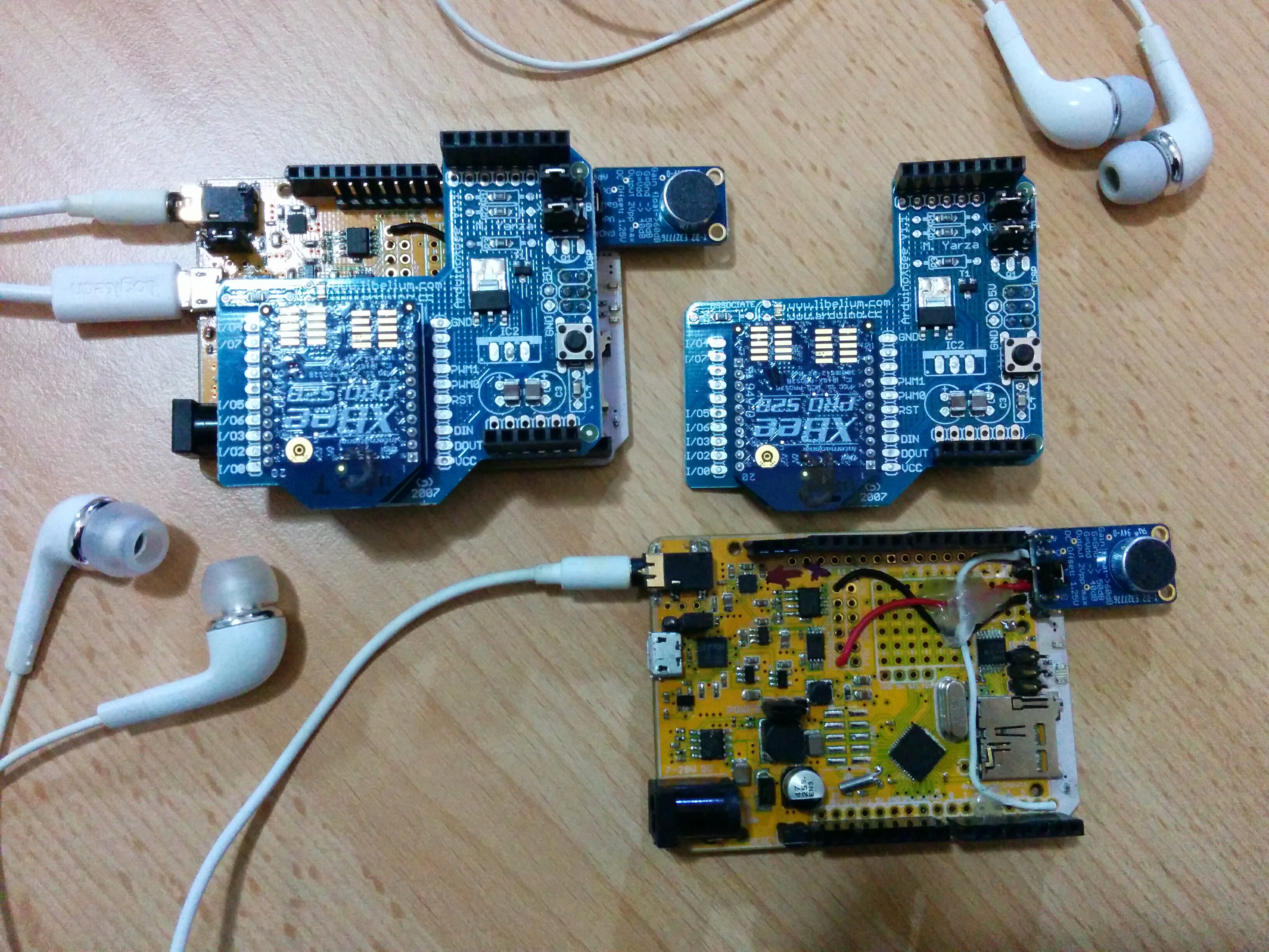
Two Goldilocks Analogue prototypes with XBee radios, and Microphone amplifiers.
The actual Walkie Talkie functionality is really only a few lines of code, but it is built on a foundation of analogue input (sampling), analogue output on the SPI bus to the MCP4822 DAC, sample timing routines, and the XBee digital radio platform. Let’s start from the top and then dig down through the layers.
XBee Radio
I am using XBee Pro S2B radios, configured to communicate point to point. For the XBee Pro there needs to be one radio configured as the Coordinator, and the other as a Router. There are configuration guides on the Internet.
I have configured the radios to wait the maximum inter-character time before sending a packet, which implies that the packets will be set only when full (84 bytes). This maximises the radio throughput. Raw throughput is 250 kbit/s, but the actual user data rate is limited to about 32 kbit/s. This has an impact on the sampling rate and therefore quality of speech that can be transmitted.
Using 10 bit samples companded using A-Law to 8 bit code words, I have found that about 3 kHz sampling generates about as much data as can be transmitted without compression. I’m leaving G.726 compression for another project.
The XBee radios are configured in AT mode, which acts as a transparent serial pipe between the two endpoints. This is the simplest way to connect two devices via digital radio. And it allowed me to do simple testing, using wire, before worrying about whether the radio platform was working or not.
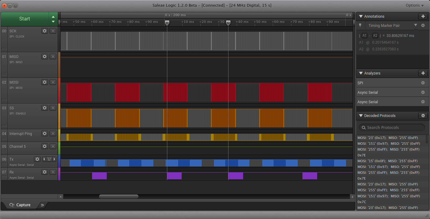
XBee Packet Reception in Purple
Looking at the tracing of a logic analyser, we can see the XBee data packets arriving on the (purple) Rx line of the serial port. The received packet data is stored into a ring buffer, and played out at a constant rate. I have allowed up to 255 bytes in the receive ring buffer, and this will be sufficient because the XBee packet size is 84 bytes.
The samples to be transmitted to the other device are transmitted on the (blue) Tx line, more or less in each sample period even though they are buffered before transmission. The XBee radio buffers these bytes for up to 0xFF inter-symbol periods (configuration), and only transmits a packet to the other endpoint when it has a full packet.
Sampling Rate
Looking at the bit budget for the transmission link, we need to calculate how much data can be transmitted without overloading the XBee radio platform, and causing sample loss. As we are not overtly compressing the voice samples, we have 8 bit samples times 3,000 Hz sampling or 24 kbit/s to transmit. This seems to work pretty well. I have tried 4 kHz sampling, but this is too close to the theoretical maximum, and doesn’t work too effectively.
Sample rate of 3,000 Hz seems to be the optimum.
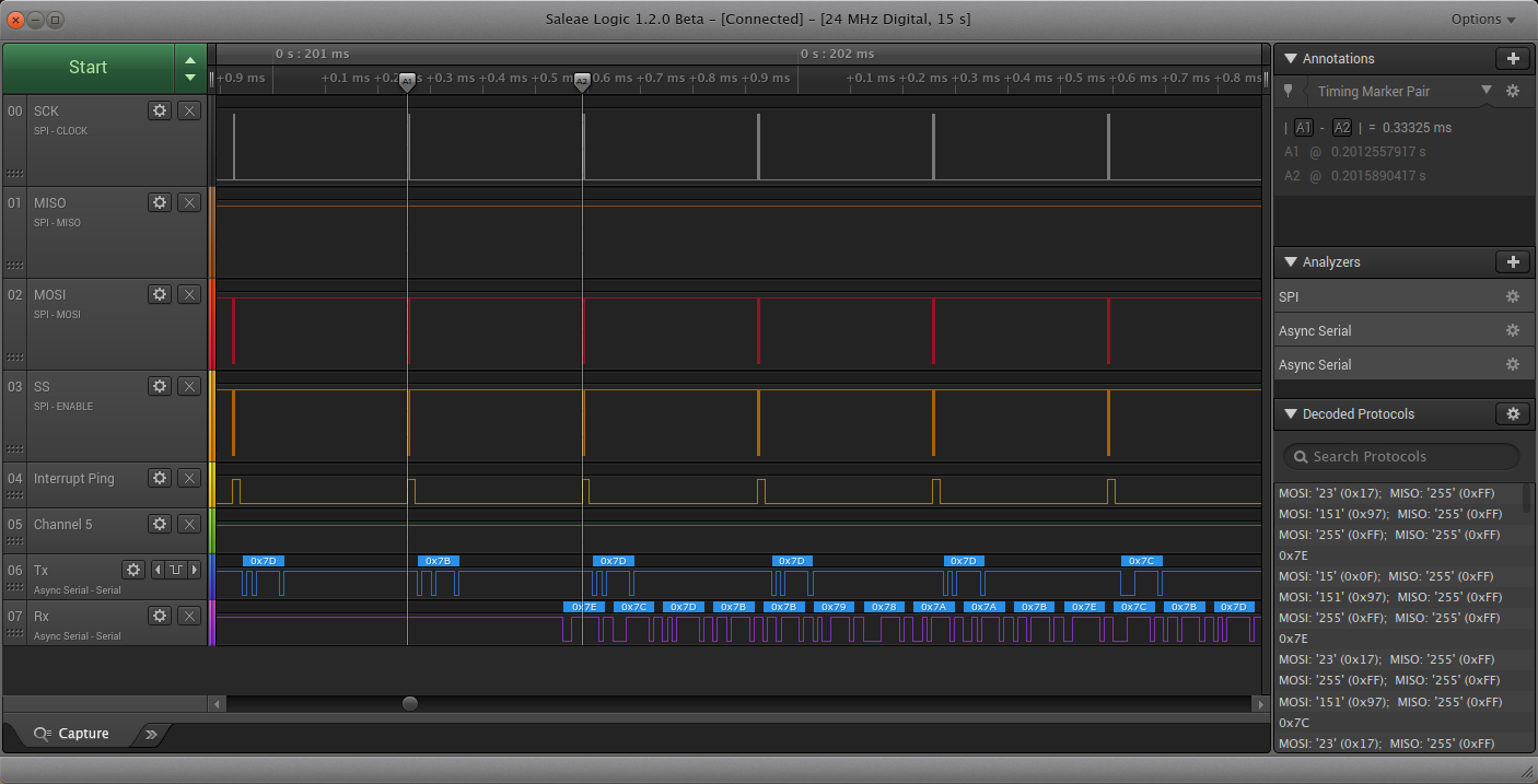
Looking at the logic analyser, we can see the arrival of a packet of bytes commencing with 0x7E and 0x7C on the Rx line. Both the Microphone amplifier and the DAC output are biased around 0x7F(FF), so we can read that the signal levels captured and transmitted here are very low. The sample rate shown is 3,000 Hz.
Sample Processing
I have put a “ping” on one output to capture when the sampling interrupt is being processed (yellow). We can see that the amount of time spent in the interrupt processing is very small for this application, relative to the total time available. Possibly some kind of data compression could be implemented.
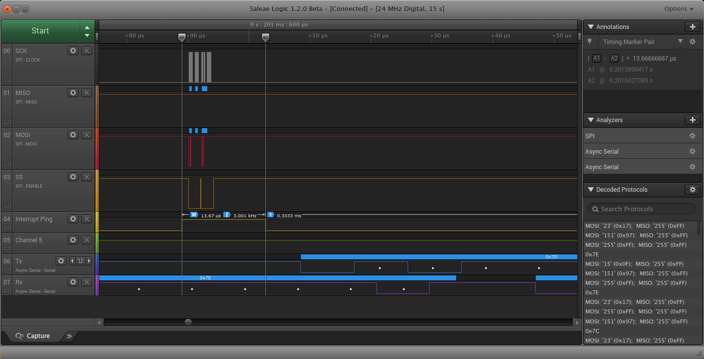
DAC and sample processing
During the sampling interrupt, there are two major activities, generating an audio output, by placing a sample onto the DAC, and then reading the ADC to capture an audio sample and transmit it to the USART buffer.
This is done by the audioCodec_dsp function, which is called from the code in a timer interrupt.
void audioCodec_dsp( uint16_t * ch_A,  uint16_t * ch_B)
{
	int16_t xn;
	uint8_t cn;
	/*----- Audio Rx -----*/

	/* Get the next character from the ring buffer. */

	if( ringBuffer_IsEmpty( (ringBuffer_t*) &(xSerialPort.xRxedChars) ) )
	{
		cn = 0x80 ^ 0x55; // put A-Law nulled signal on the output.
	}
	else if (ringBuffer_GetCount( &(xSerialPort.xRxedChars) ) > (portSERIAL_BUFFER_RX>>1) ) // if the buffer is more than half full.
	{
		cn = ringBuffer_Pop( (ringBuffer_t*) &(xSerialPort.xRxedChars) ); // pop two samples to catch up, discard first one.
		cn = ringBuffer_Pop( (ringBuffer_t*) &(xSerialPort.xRxedChars) );
	}
	else
	{
		cn = ringBuffer_Pop( (ringBuffer_t*) &(xSerialPort.xRxedChars) ); // pop a sample
	}

	alaw_expand1(&cn, &xn);	// expand the A-Law compression

	*ch_A = *ch_B = (uint16_t)(xn + 0x7fff); // move the signal to positive values, put signal out on A & B channel.

	/*----- Audio Tx -----*/

	AudioCodec_ADC( &mod7_value.u16 );	// sample is 10bits left justified.

	xn = mod7_value.u16 - 0x7fe0;	// center the sample to 0 by subtracting 1/2 10bit range.

	IIRFilter( &tx_filter, &xn);	// filter transmitted sample train

	alaw_compress1(&xn, &cn);	// compress using A-Law

	xSerialPutChar( &xSerialPort, cn);	// transmit the sample
}
I am using the AVR 8 bit Timer0 to generate the regular sample intervals, by triggering an interrupt. By using a MCU FCPU frequency which is a binary multiple of the standard audio frequencies, we can generate accurate reproduction sampling rates by using only the 8 bit timer with a clock prescaler of 64. To generate odd audio frequencies, like 44,100 Hz, the 16 bit Timer1 can be used to get sufficient accuracy without requiring a clock prescaler.
The ATmega1284p ADC is set to free-run mode, and is scaled down to 192 kHz. While this is close to the maximum acquisition speed documented for the ATmega ADC, it is still within the specification for 8 bit samples.
ISR(TIMER0_COMPA_vect) __attribute__ ((hot, flatten));
ISR(TIMER0_COMPA_vect)
{
#if defined(DEBUG_PING)
  // start mark - check for start of interrupt - for debugging only (yellow trace)
  PORTD |= _BV(PORTD7); // Ping IO line.
#endif

  // MCP4822 data transfer routine
  // move data to the MCP4822 - done first for regularity (reduced jitter).
  DAC_out (ch_A_ptr, ch_B_ptr);

  // audio processing routine - do whatever processing on input is required - prepare output for next sample.
  // Fire the global audio handler which is a call-back function, if set.
  if (audioHandler!=NULL)
    audioHandler(ch_A_ptr, ch_B_ptr);

#if defined(DEBUG_PING)
  // end mark - check for end of interrupt - for debugging only (yellow trace)
  PORTD &= ~_BV(PORTD7);
#endif
}
This interrupt takes 14 us to complete, and is very short relative to the 333 us we have for each sample period. This gives us plenty of time to do other processing, such as running a user interface or further audio processing.
SPI Transaction
At the final level of detail, we can see the actual SPI transaction to output the incoming sample to the MCP4822 DAC.
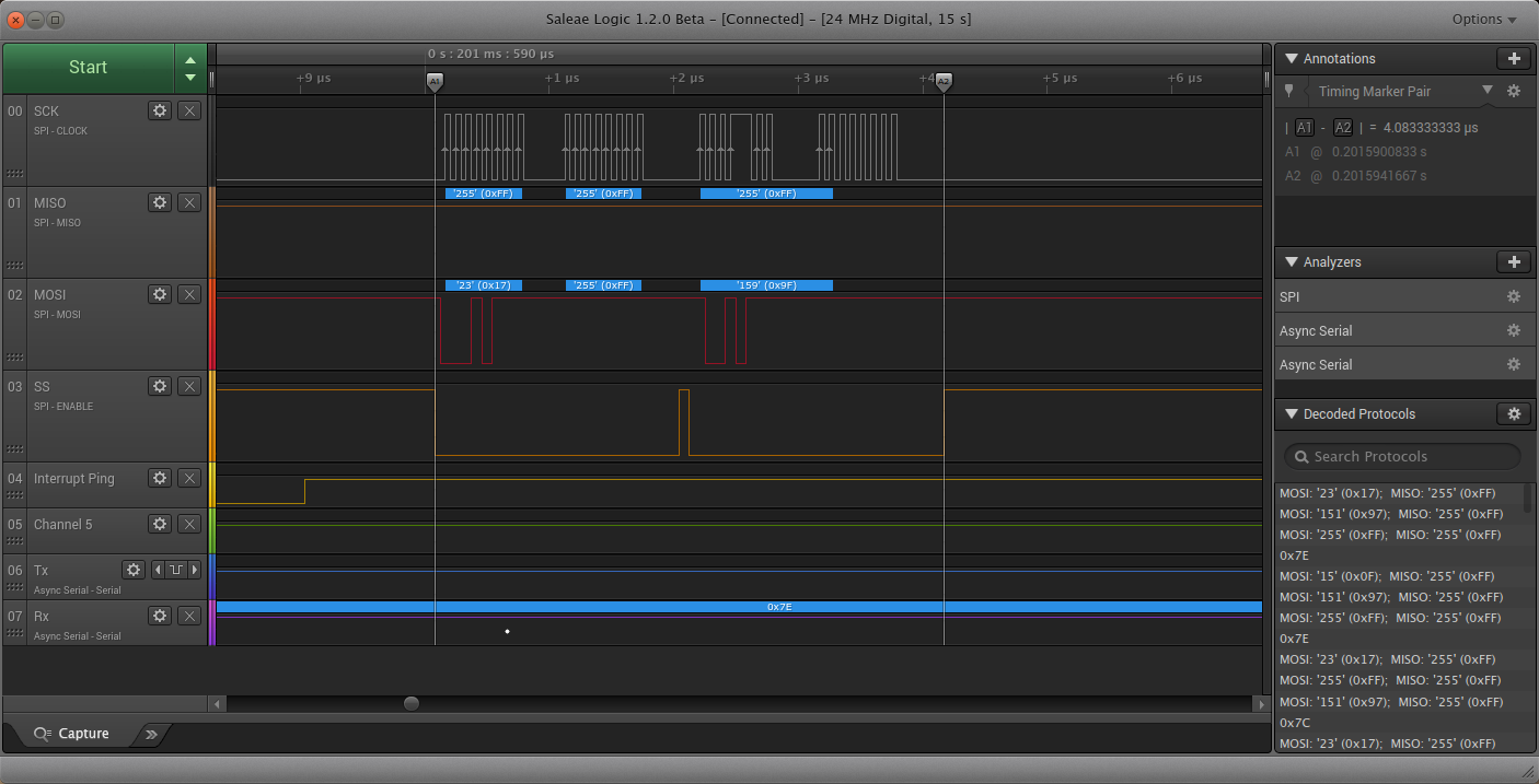
SPI MCP4822 DAC Transaction
As I have built this application on the Goldilocks Analogue Prototype 2 which uses the standard SPI bus, the transaction is normal. My later prototypes are using the Master SPI Mode on USART 1 of the ATmega1284p, which slightly accelerates the SPI transaction through double buffering, and frees the normal SPI bus for simultaneous reading or writing to the SD Card or SPI Memory, for audio streaming. In the Walkie Talkie application there is no need to capture the audio, so there’s no down side to using the older prototypes and the normal SPI bus.
void DAC_out(const uint16_t * ch_A, const uint16_t * ch_B)
{
  DAC_command_t write;

  if (ch_A != NULL)
  {
    write.value.u16 = (*ch_A) >> 4;
    write.value.u8[1] |= CH_A_OUT;
  }
  else // ch_A is NULL so we turn off the DAC
  {
    write.value.u8[1] = CH_A_OFF;
  }

  SPI_PORT_SS_DAC &= ~SPI_BIT_SS_DAC; // Pull SS low to select the Goldilocks Analogue DAC.
  SPDR = write.value.u8[1]; // Begin transmission ch_A.
  while ( !(SPSR & _BV(SPIF)) );
  SPDR = write.value.u8[0]; // Continue transmission ch_A.

  if (ch_B != NULL) // start processing ch_B while we're doing the ch_A transmission
  {
    write.value.u16 = (*ch_B) >> 4;
    write.value.u8[1] |= CH_B_OUT;
  }
  else // ch_B is NULL so we turn off the DAC
  {
    write.value.u8[1] = CH_B_OFF;
  }

  while ( !(SPSR & _BV(SPIF)) ); // check we've finished ch_A.
  SPI_PORT_SS_DAC |= SPI_BIT_SS_DAC; // Pull SS high to deselect the Goldilocks Analogue DAC, and latch value into DAC.

  SPI_PORT_SS_DAC &= ~SPI_BIT_SS_DAC; // Pull SS low to select the Goldilocks Analogue DAC.
  SPDR = write.value.u8[1]; // Begin transmission ch_B.
  while ( !(SPSR & _BV(SPIF)) );
  SPDR = write.value.u8[0]; // Continue transmission ch_B.
  while ( !(SPSR & _BV(SPIF)) ); // check we've finished ch_B.
  SPI_PORT_SS_DAC |= SPI_BIT_SS_DAC; // Pull SS high to deselect the Goldilocks Analogue DAC, and latch value into DAC.
}
Wrap Up
Using a few pre-existing tools and a few lines of code, it is possible to quickly build a digitally encrypted walkie talkie, capable of communicating (understandable, but certainly not high quality) voice. And, there ain’t no CB truckers going to be listening in on the family conversations going forward.
This was a test of adding microphone input based on the MAX9814 to the Goldilocks Analogue. I will be revising the Prototype 3 and will add in a microphone amplification circuit to support applications needing audio input, like this walkie talkie example, or voice changers, or vocal control music synthesizers.
I’m also running the ATmega1284p devices at the increased frequency of 24.576 MHz, over the standard rate of 20 MHz. This specific frequency allows very precise reproduction of audio samples from 48 kHz down right down to 4 kHz (or even down to 1,500 Hz). The extra MCU clock cycles per sample period are very welcome when it comes to generating synthesised music, or encoding audio samples.
Code as usual on Github AVRfreeRTOS repository. Also, a call out to Shuyang at SeeedStudio who’s OPL is awesome, and is the source of many components and PCBs.

Pingback: Goldilocks Analogue Synthesizer | feilipu
Pingback: Goldilocks Analogue – Prototyping 4 | feilipu
Pingback: Goldilocks Analogue – Testing 4 | feilipu