Freetronics freeRTOS Retrograde Real Time Clock (DS1307) – Part 3 Final

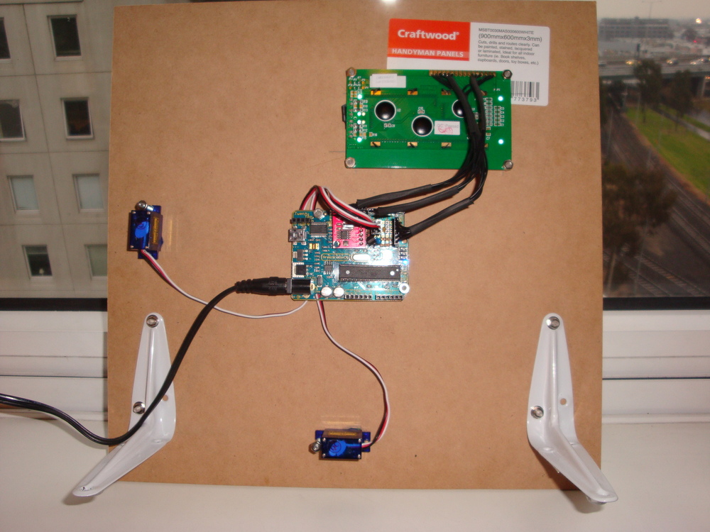
In Part 2  I promised to build a very stylish finished product, that could be displayed with pride. Well, I don’t think I’ve quite achieved that. But, at least now I consider the project finished, and now have the confidence to get on with other projects.

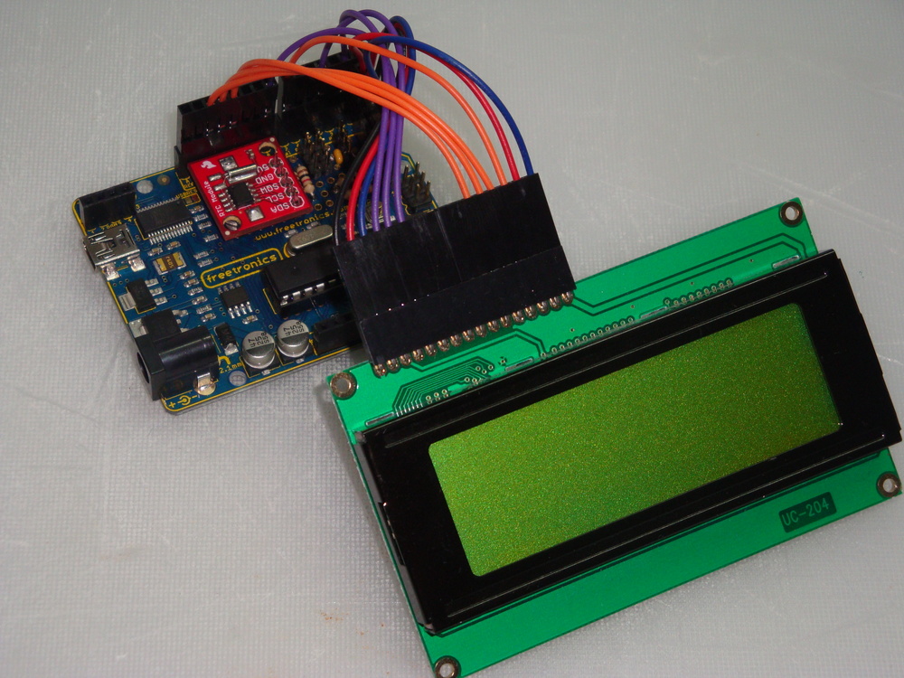
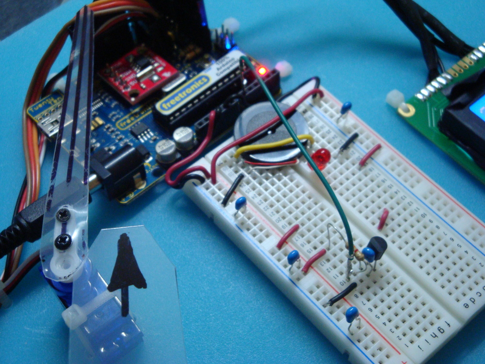
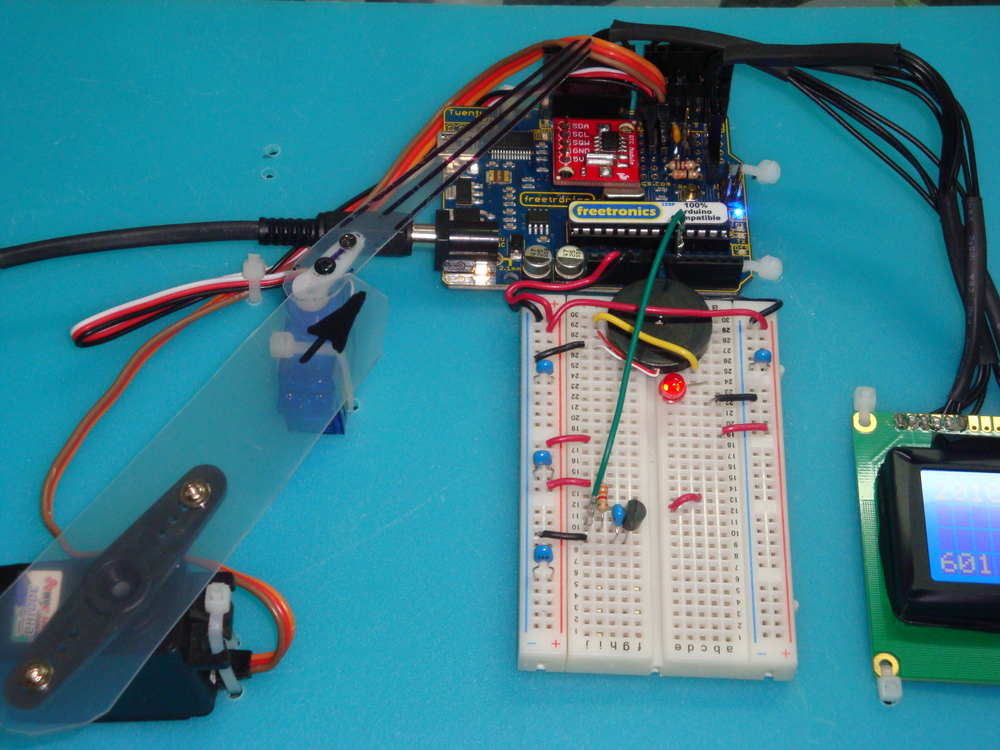
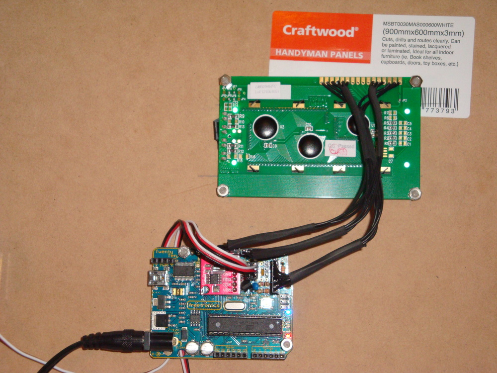
I have mounted some tiny servos, the funky white on blue LCD display, and the Freetronics 2010 board on some Craftwood. Cutting the hole for the LCD was a bit hit & miss, using a carving knife to shape the hole, and managing not to loose any fingers in the process.

Dsc04060Dsc02851

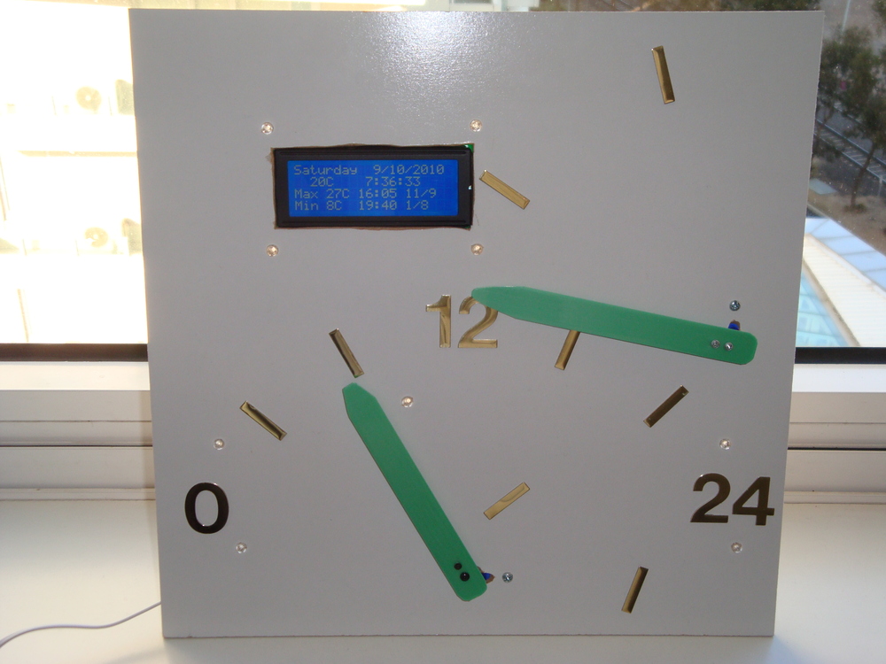
The hour servo is mounted at the bottom of the board, and travels clockwise from midnight, with noon vertical, until it re-tours to 0 on the stroke of midnight. The hour hand travels clockwise from 0 minutes at the bottom, over 30 minutes horizontal, to 59 minutes at the top of the stroke. At 0 minutes, the minute hand re-tours to 0 at the bottom. I find the movement of the servos on the stroke of the hour somewhat like a chime. Not too oppressive, but enough to draw my attention to the passing of another hour.

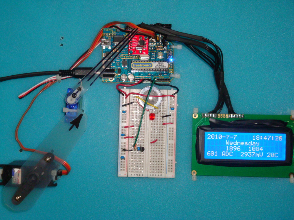
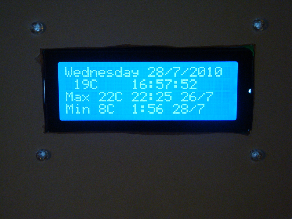
As the 4 line LCD has so much screen real estate, I have added the maximum and minimum temperature display, with hour, day and month when each extreme was reached.

Adding the LM335Z Temperature IC was discussed in Part 2. I found that the accuracy of the LM335Z IC could be improved by firstly knowing exactly what the Vcc was for operating the AVR device. Measuring this, and putting it in the calculation enabled enough accuracy to be found. Using the 5V regulator on the Freetronics 2010 delivered 4.97V for me, and this value is hard coded into the code. I have several LM335Z devices and they have different offsets, which is adjusted by modifying the subtraction in the Kelvin to Celsius calculation. As the LM335Z is accurate once the offset is established, there is no need to operate it in the “accurate” mode, IMHO, given we have software to make the adjustments it needs.

Dsc02855Dsc02852Dsc02854

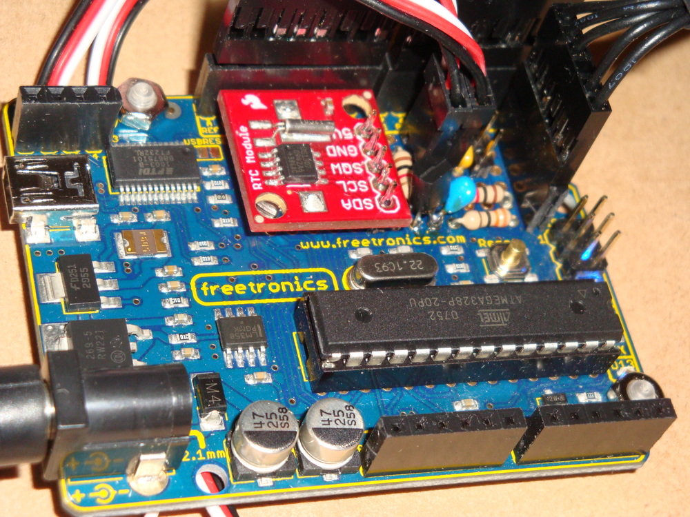
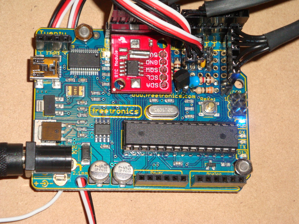
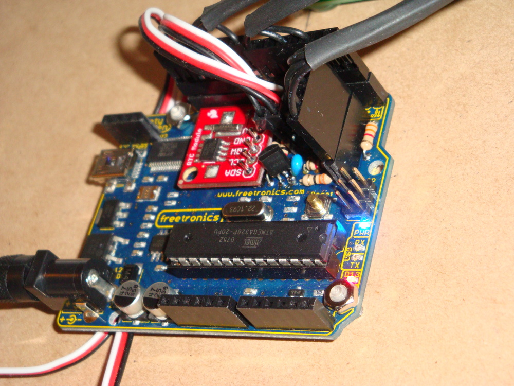
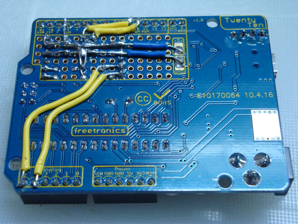
The instability in the temperature readings discussed in Part 2 was caused by the long wires to the sensor. Once the device was fixed into the prototyping area on the 2010, together with bypass capacitor, the stability of readings improved greatly. However, during testing, I noted that the maximum values were reading very high. These false high maximum values were caused because the ADC process was sampling during a servo move. The servos consume a lot of power, and this causes voltage drop on Vcc. Hence the reference voltage for the ADC is no longer accurate.

Dsc02845Dsc02847

To prevent the ADC from operating during the servo moves, I simply used one of the freeRTOS semaphores I established previously. I use semaphores to control access to the LCD, the I2C and to the ADC. Use of a semaphore enables independent processes to share a single hardware resource without conflicts developing. The fix for the erroneous high maximums was done simply by taking the ADC semaphore (to prevent the ADC reading process from starting) during times when the servos are being instructed to move. Simple, with freeRTOS to manage the process interaction for me.

ERRATA

The code included in the updated source does not properly fix the issue of false maximum temperatures. It incorrectly releases the ADC semaphore immediately following resetting the PWM values. This means that the hands can still be moving when the ADC process gets unblocked which causes false maximums, because of voltage droop in Vcc, typically at midnight when both hands are in motion.

The fix is to move the vTaskDelay call between the set_PWM_hardware and xSemaphoreGive calls. I also increased it to 2000 milli Seconds too, to ensure the hands are really stopped before the ADC process gets unblocked.

set_PWM_hardware( servoHours_uS, servoMinutes_uS );

vTaskDelay( 2000 / portTICK_RATE_MS ); // a 2 second delay to ensure the hands have properly stopped.

xSemaphoreGive( xADCSemaphore );


END ERRATA

Another piece of code added since Part 2 is to write the maximum and minimum temperatures and the times the extremes occurred into the EEPROM available on the 2010. The functions to use the EEPROM are available in the AVR library and are very straightforward to use. Having a permanent record of temperature extremes is perhaps one thing this clock does, that other clocks in my house can’t do.

There are a lot of comments in the updated freeRTOS Retrograde Clock code, now hosted at Practical Arduino. As a reminder the code uses the AVR and Pololu Libraries, so these both need to be installed before you compile.


Freetronics freeRTOS Retrograde Real Time Clock on PS3 – Part 2a

Just for interest, I decided to see how the support for AVR or Arduino was on the PS3.

Using the standard tools on Ubuntu Lucid 10.4 from my OtherOS installation. A quick search for AVR on synaptic got the avr-lib, avr-gcc, and avrdude tools needed. No special versions, just straight off the repository.

Then, I followed the link to the Pololu Libraries in my Part 2 post, made the changes to OrangutanLCD.h as noted, hit make, and crossed my fingers. No issue. It all worked. sudo make install to put the files in right place.

OK. does the PS3 USB platform recognise the FTDI 232RL USB chip on the Freetronics 2010? Yes. Another hurdle cleared, with no issues.

With that step done, it was simple to download the retrograde files from Practical Arduino as noted in Post 2, extract them. Hit make program and off we go. avrdude works as expected, and the new code is loaded as normal.

I’d say the whole test was over faster than it has taken to type this note.

I should be over this, but I get so happy when technology just works… particularly when it is all free. Got to love your FOSS.

One small issue. There doesn’t seem to be a release of Arduino tools for PS3 (PowerPC). Pity about that. Perhaps in another repository…

Freetronics freeRTOS Retrograde Real Time Clock (DS1307) – Part 2

Part 2 of this project involved learning how to use hardware PWM to control servos. And, then to make the clock actually work with retrograde analogue hands.

First the functional definition. A retrograde movement in horological terms is where the indicators or hands spring back to their home or 0 position at the end of their cycle. So for a minute hand, after 59 minutes and 59 seconds, its next movement would be to reverse move to home at 0 minutes. For the hour hand this could happen after 12 hours or 24 hours. 24 hours is the case that I have chosen to implement. The idea is to have the hour hand trace out a day from sunrise in the east, to vertical noon, and to set in the west.

In part 1, I added the servo headers to align with the Arduino Digital Pins 5 & 6. These pins are driven by the Timer 0 PWM hardware. Following quite a few evenings trying to understand how to generate PWM using the hardware (OK, I’m a bit slow), I realised that it is not very easy to get a good servo signal out of Timer 0 or Timer 2.

To generate the right signal for a servo, you need to produce a pulse every 20mS (50Hz). The width of the pulse should be 1.5mS to get the neutral position. Depending on the servo design, pulses with width from around 0.8mS to around 2.2mS (repeated every 20mS) will drive it to either end of its range. Depending on the servo, 0.8mS may drive it clockwise or anticlockwise. I have both in the clock. For example, the “hour” servo goes clockwise with a wider pulse. The “minute” servo is the reverse case.

The main issue with Timer 0 and Timer 2 is that they are 8 bit timers, counting to 255 before resetting to 0 (ideally after 20mS). Since the required pulses are between 0.8mS and 2.2mS, there are only about 12 “positions” available for the servo to take. Not enough to allow a minute hand to indicate 60 different positions.

Therefore it became clear that, for this application, it was only possible to use the 16 bit Timer 1 to control the servos.

Setting up Timer 1 is relatively easy, once that decision had been made, so the code was implemented. But, this meant that I had to reconnect the servo headers to Arduino Digital Pin 9 and Pin 10, which are driven by the Timer 1 PWM hardware.

Also, in the pictures below, I have added a header to allow power, LCD backlight (32Ohm), and contrast (1kOhm), connections to the standardised HD44780 LCD.

Dsc02787Dsc02791Dsc02789

Ok, so here’s the issue. I’m using the Pololu Libraries for writing to the LCD, and the standard connection for the data line 4 on the HD44780 LCD goes to Arduino Pin 9. The same pin I need for the Timer 1 PWM. Ouch.

Modifying the library is not too difficult. We can move the Data line attached to Pin 9 onto Pin 11, and all is well. This is done in the following file.

~/libpololu-avr/src/OrangutanLCD/OrangutanLCD.h

The changes are noted in the #define lines below

#define LCD_DB4                PORTB3        // Was PORTB1. Use PORTB3 to avoid the Timer1 pins.
#define LCD_DB5                PORTB4        // PB4
#define LCD_DB6                PORTB5        // PB5
#define LCD_DB7                PORTD7        // PD7

//    PortB:     7 6 5 4 3 2 1 0
//  LCD Data:      2 1 0            Use DB3 to avoid Timer1 pins.
//  LCD Data:      2 1     0
//
//  PortD:     7 6 5 4 3 2 1 0
//  LCD Data:  3

#define LCD_PORTB_MASK            ((1 << LCD_DB4) | (1 << LCD_DB5) | (1 << LCD_DB6))  // Modified to avoid using DB1
#define LCD_PORTD_MASK            (1 << LCD_DB7)
#define LCD_PORTB_DATA(data)    ((data & 0x07) << 3)  // Modified the data mask to avoid using DB1
#define LCD_PORTD_DATA(data)    ((data & 0x08) << 4)

The below pictures show the LCD pin layout.
<blockquote”>Red = VCC

Black = GND

BLUE = Voltage for contrast or backlight

Orange = Data lines (4-bit: DB4 – DB7) PB3 (not PB1), PB4, PB5, and PD7. Arduino Digital pins 11 (not 9), 12, 13, and 7

Purple = Control lines (RS, R/W, E) PD2, PB0, and PD4. Arduino Digital pins 2, 8, and 4

Dsc02793Dsc02796

So now we have PWM for our retrograde analogue hands, and a LCD display.

But wait, there’s more…

There’s too much display going to waste, so let’s add something else… Hmm… Temperature, and time, make a min/max thermometer that can show what time each extreme temperature was reached during the day.

Quickly getting a LM335Z temperature sensor, I’m now testing whether the 10bit ADC is good enough to generate reasonable temperature readings from the device. At full range of 5000mV across 1024 levels, we have about 4.88mV per level. The LM355Z produces 10mV per degree, so we should be able to get 0.5 degree accuracy. If everything is perfect.

Currently the temperature gauge works, but the accuracy is still a work in progress, as are the min / max functions. The LM335Z has only two connections, and is biased by a single resistor (3200 Ohm), so it will fit into the board if that is all that is needed. Getting perfection may require addition of decoupling capacitors on AREF and across the sensor, but I’m still
experimenting with this.

Dsc02838Dsc02839

The overall working product is shown below. But wait, there’s more…

I was not happy with using resistors to tie up the SCL and SDA lines high for the I2C bus, as it should be possible to use the internal pull up resistors in some situations (according to the Atmel datasheet).

So using a new Freetronics 2010 from Little Bird Electronics, the clock is now rebuilt without external pull up resistors. The I2C code is modified to only pull up the lines between the start and stop bus instructions. The levels are messy (not showing sharp transitions in my SLO) but, never the less the code and the clock works.

The working device is shown below. Note the rather funky white on blue display I got from Sparkfun.

Dsc02842

In the years since this instruction was writen, I’ve migrated to Github. So the code is hosted here. The freeRTOS code is also posted on Github. I used the Pololu Library for writing to the display, so it needs to be installed along with the normal AVR libraries.

Part 3 will look at how to build a really stylish clock face that can be shown off in public

Freetronics 2010 (Arduino Duemilanova) freeRTOS Real Time Clock (DS1307) – Part 1

I was pondering the blank space on my 2010 recently, and combining that space with some other left over kit from Dogbot, I decided to make a dual retrograde analogue clock.

To build the clock I have the choice of either using NTP to sync a wireless enabled device, or use a RTC clock and re-set it every month or so. For this iteration, I’ve decided to go the RTC route.

Actually, reading this Tronixstuff page also got me going on the idea of using a DS1307 chip, and also Sparkfun makes a nice module that just happens to fit in the vacant space on the 2010. So, I bought one from LittleBird Electronics.

Only other thing to do was to add some servo headers, to get me going with the analogue clock face (using servos).

The picture below shows the layout. I tried a few different options, but this layout seems to only affect the legibility of the pin labelling. Other layouts mask the crystals close together, and I’m not sure how that would affect clock accuracy, or prevent the battery from being removed (9 years later).

Dsc02777

Yes, everything fits. Now to the soldering iron.

Dsc02779

Ok now it is soldered together, and everything looks reasonably fine.

Dsc02780Dsc02781

Now, on the test bed, I have the RTC clock working well using my beloved freeRTOS, and can get on with using the servos to drive analogue hands.

Dsc02785Dsc02784

In the years since this instruction was writen, I’ve migrated to Github. So the code is hosted here. The freeRTOS code is also posted on Github. I used the Pololu Library for writing to the display, so it needs to be installed along with the normal AVR libraries.

Part 2 looks at building the PWM control for the retrograde hands, and adding a temperature function.

Freetronics 2010 (Arduino Duemilanova) Overclocking & Review

Recently, I picked up a Freetronics 2010 from Little Bird Electronics.

Dsc02744

I thought that it would make a nice upgrade to my Dogbot test bed. It uses the same USB connector as Dogbot’s Pololu SVP, so it saves me from keeping different USB cables handy, but is in every way 100% the same as the Arduino Duemilanove that I’ve been using up to now.

But, everything I own is hacked in some way. So as usual, I thought that the 2010 could be improved, just as I’ve improved the Duemilanove before it, by overclocking it to 22.1184MHz.

Overclocking to 22.1184MHz

So why change the clock frequency to this odd number of 22.1184MHZ, and not to 20MHz which would be in specification?

It turns out that because of the binary and integer world the 2010 and the Duemilanova ATmega328p MCU live in, it is much better have a “nice” binary and integer friendly base frequency. Unfortunately, although 16MHz on a 2010 or Arduino sounds nice, from the point of view of integer programming, clock scaling, and UART interfacing, it is difficult to get clean integer numbers.

A small example.
16MHz clock scaled to 115200baud = 138.888888889 so rounding gives an error term.
20MHz clock scaled to 115200baud = 173.6111111111 so, again, rounding gives an error term.
22.1184MHz clock scaled to 115200baud = 192 with no rounding error.

Also, even though we are getting 16,000,000 instructions per second out of a standard?2010, and that should be enough for any application. I can get 22,118,400 or a 38% improvement for the cost of a few cents. So, why wouldn’t you?

What kind of issues can occur?

Well, over-clocking means that the ATmega328p is out of specification. But, I’m not too worried about pushing specification on this project, as the 328p is certified for an industrial operating temperature range, which is way outside of my operating temperature… There are also unverified reports of AVR ATmegas working successfully up to 32MHz.

In the overall scheme of things, raising the clock frequency on the AVR ATmega328p above specification by 10% to 22.1184MHz is no big deal.

Upgrading Process

1. Obtain a 22.1184MHz HC49/US crystal from Digikey They’re pretty cheap. Buy a bag in case of accidents.

Dsc02746Dsc02747

2. Use a knife tip under the existing 16MHz crystal to give you a lever to pressure it into removal, without burning your fingers. It will get very hot!

3. Turn over the board and use a soldering iron to heat the joints, whilst leaning on the knife to lever out the 16MHz crystal. Once it is removed, use some solder wick or similar to remove excess solder, and make it easier to insert and solder the new 22.1184MHz crystal.

Dsc02751Dsc02750Dsc02755

4. Building a new bootloader. In replacing the crystal, the 2010 is effectively bricked. You can no longer communicate with it using the standard bootloader. It is now running too fast and out of specification for avrdude to communicate with it, so we have to compile and burn a new boot loader before we go any further. I choose to use the Adaboot328 bootloader from Ladyada. It resolves a few known issues with Arduino compatible boards, and is easy to compile.

In the ATmegaBOOT_xx8.c file, change the UART baud rate to 115200, if you use avrdude for programming (if using Arduino IDE, do not change this from 19200). Who has time to wait around these days for 19200 baud, anyway?

/* set the UART baud rate */
#define BAUD_RATE?? 115200

In the Makefile, change the AVR_FREQ value to 22118400L for the adaboot328: TARGET.

adaboot328: TARGET = adaboot328
# Change clock frequency from 16000000L
adaboot328: AVR_FREQ = 22118400L

Then, compile the bootloader, and keep it safe.

5. Prepare an ISP. There are many alternative ways to do this, and here is not the place to describe the alternatives. Suffice to say that I used the AVRISP method in the Arduino-0018 IDE. I’ve struggled with avrdude (which I otherwise use for everything) as a bootloader ISP. I don’t know why, but I can’t make it work.

It happens that I have a standard Arduino clone available, which I prepare as the AVRISP, by uploading the following sketch File>Examples>ArduinoISP.

6. To be able to use Arduino IDE to burn our special bootloader, you have to replace the standard ATmegaBOOT_168_atmega328.hex bootloader file, found in ~arduino/bootloaders/atmega/ with our newly generated file. And, to make things simple, I just rename or remove the standard one, and replace it with our newly prepared and renamed bootloader with this name
ATmegaBOOT_168_atmega328.hex.

7. Connect our Freetronics 2010 up using the AVRISP connections, described on the Arduino web site. Make sure we have the right board type selected; it should be Duemilanova w/ ATmega328. Then using the Arduino IDE use Tools > Burn Bootloader > w/ Arduino as ISP.

Dsc02756

8. Program a sketch using either the Arduino IDE, or using avrdude, remembering that the baudrate is set to 115200. And, enjoy.

Conclusions regarding the Freetronics 2010.

Its a very well designed and produced device, that is 100% compatible with the Arduino Duemilanova. Some advantages are: the mounting holes are slightly larger so cable ties go through nicely, smaller USB connector is more common than the B connector used on Duemilanova, and there’s no solder in the holes for the X3 connector so it is easy to add headers to make it possible to burn its own bootloader (if you want).

It runs my freeRTOS build with no problems, as seen in this demo on my Dogbot test bed with a Robot Electronics Thermopile, and Sharp IR Distance sensor.

Dsc02760Dsc02761