Melding freeRTOS with ChaN’s FatF & HD44780 LCD on Freetronics EtherMega

This post is a bit of a mixed bag, describing some software and hardware integration, together with some raving about a great tool I’ve been using. So, let’s get started.

Platform

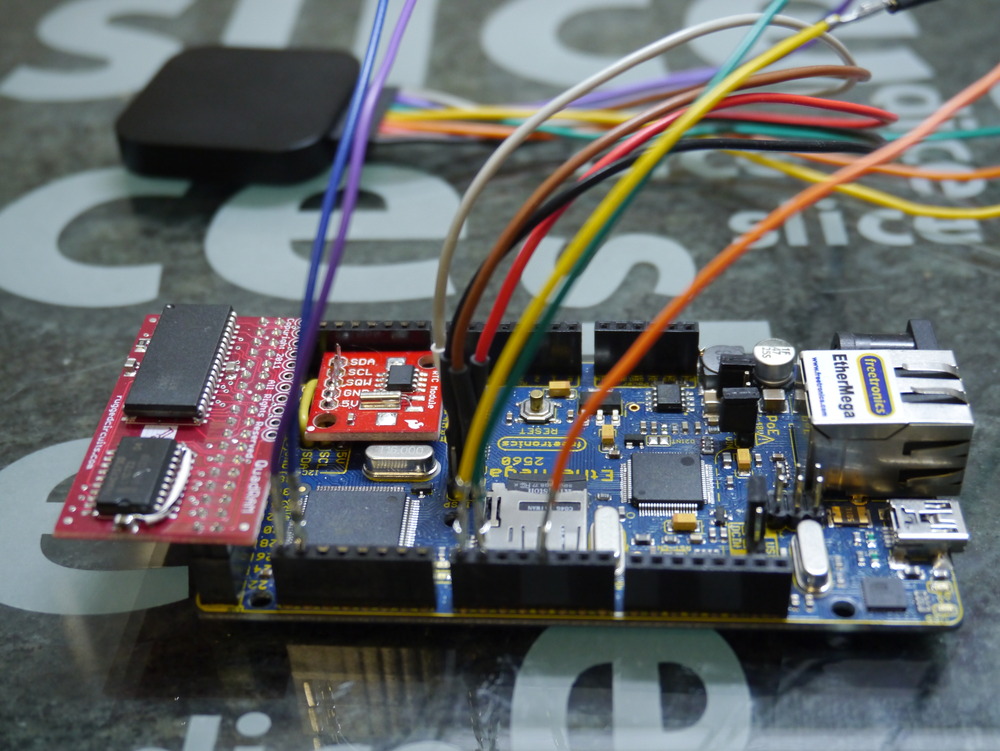
Some time ago I got a Freetronics EtherMega, which is essentially an Arduino Mega2560 with an integrated Wiznet W5100 Ethernet interface, and a MicroSD card cage. I’ve introduced this product and the use of freeRTOS here.

EtherMega (Arduino Mega 2560) and freeRTOS

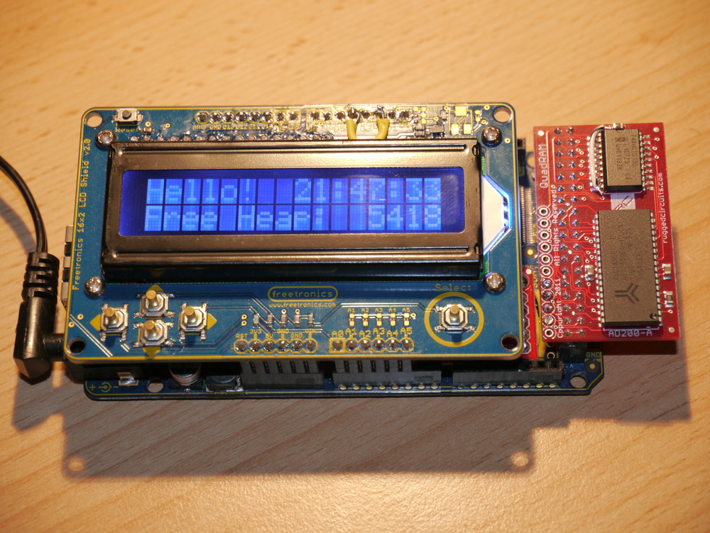
One great thing about the ATmega2560 used in the EtherMega, and the Arduino Mega2560, is the availability of an external memory bus. I’ve been using a Rugged Circuits QuadRAM, and now have ordered three more of their MegaRAM devices, and intend to make the ATmega2560 my standard platform. Why three? Well everyone knows that good things come in threes.

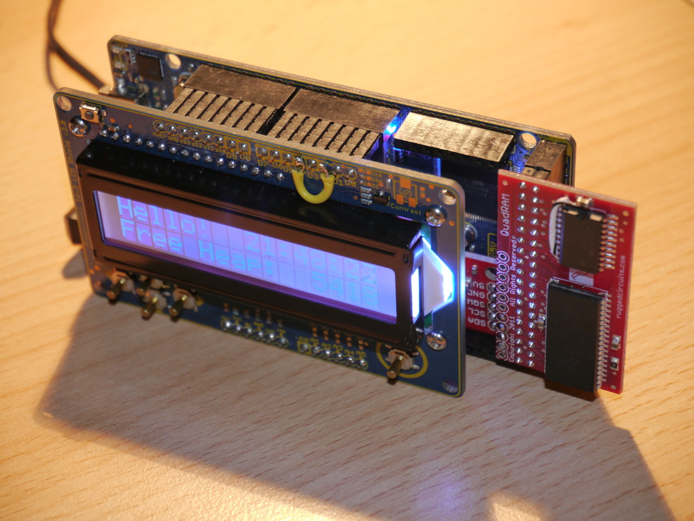
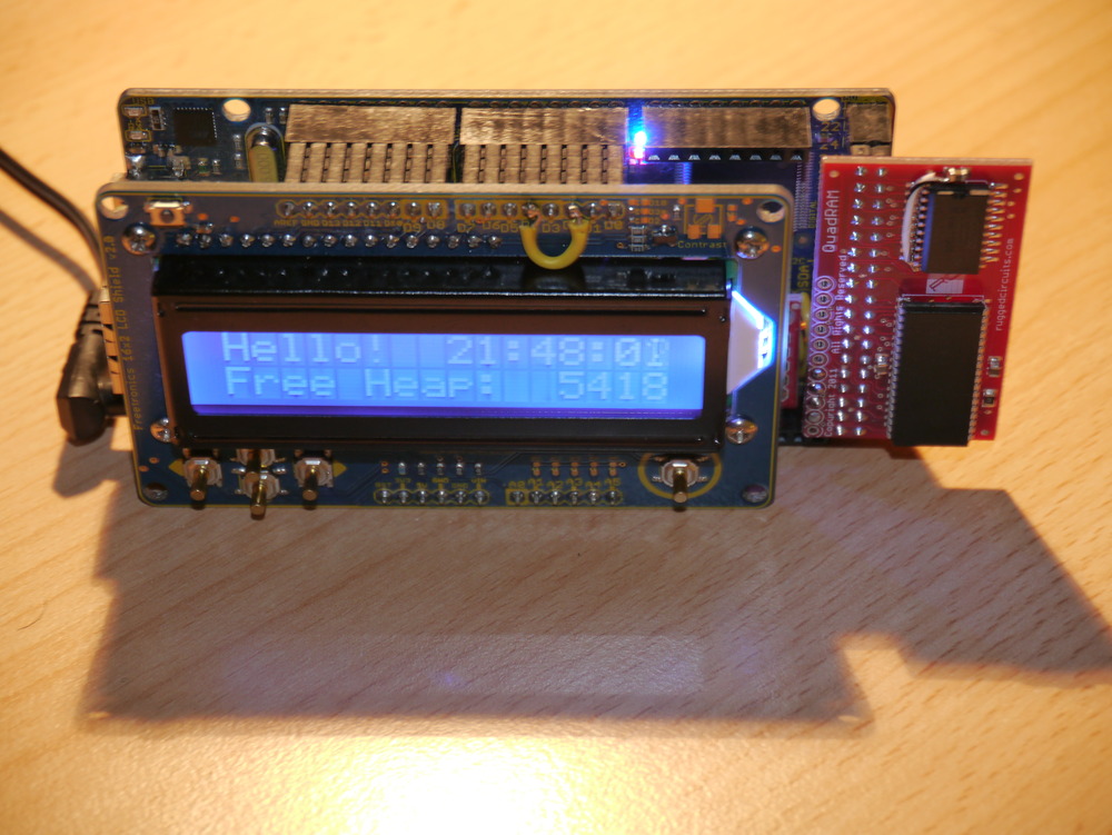
QuadRAM (512kByte) on Freetronics EtherMega (Arduino) ATmega2560 with freeRTOS

I’m actually preferring the Rugged Circuits MegaRAM which has only 128kBytes of RAM, so it won’t be as flexible for bank switching as its big brother. Also its chip select line is reversed (note to self to fix this in the driver). But, simply having 64kBytes of normal extended RAM plus another 56kBytes of special purpose (bank switched) RAM seems like it wil be sufficient for the duration. I’ve bought a couple to go on some Android ADK devices, that I’ll write about soon.

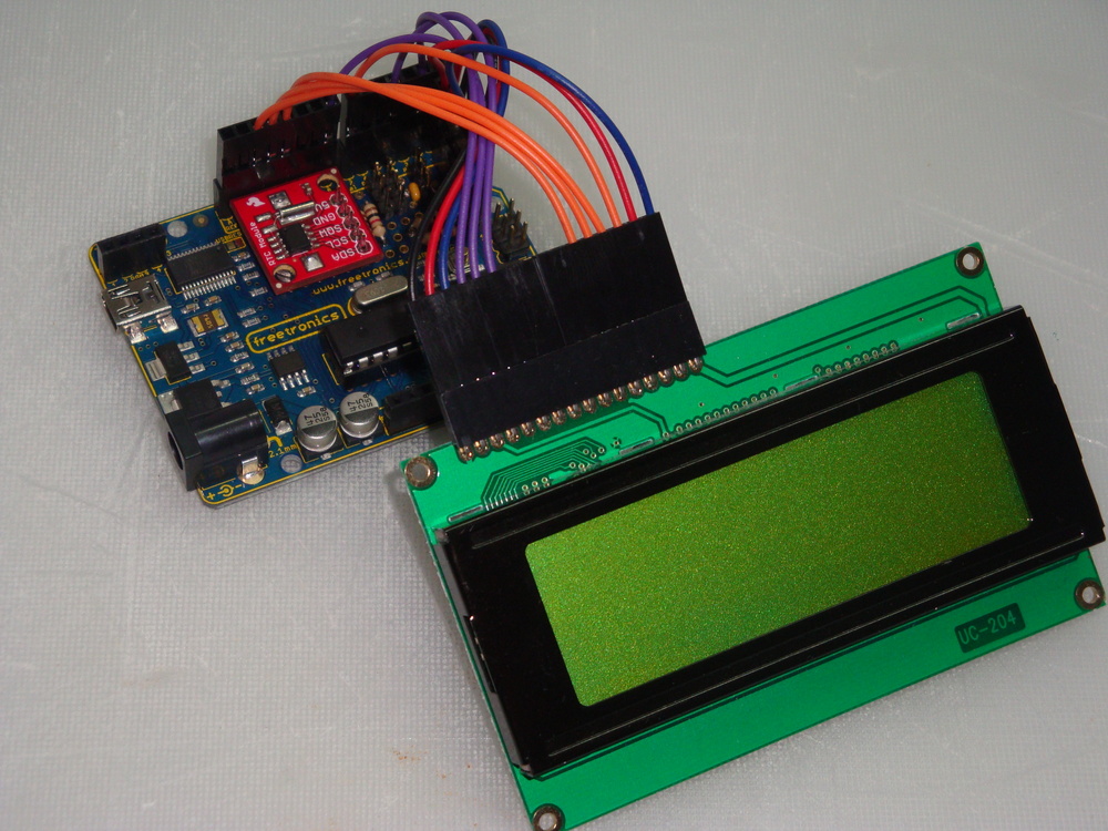
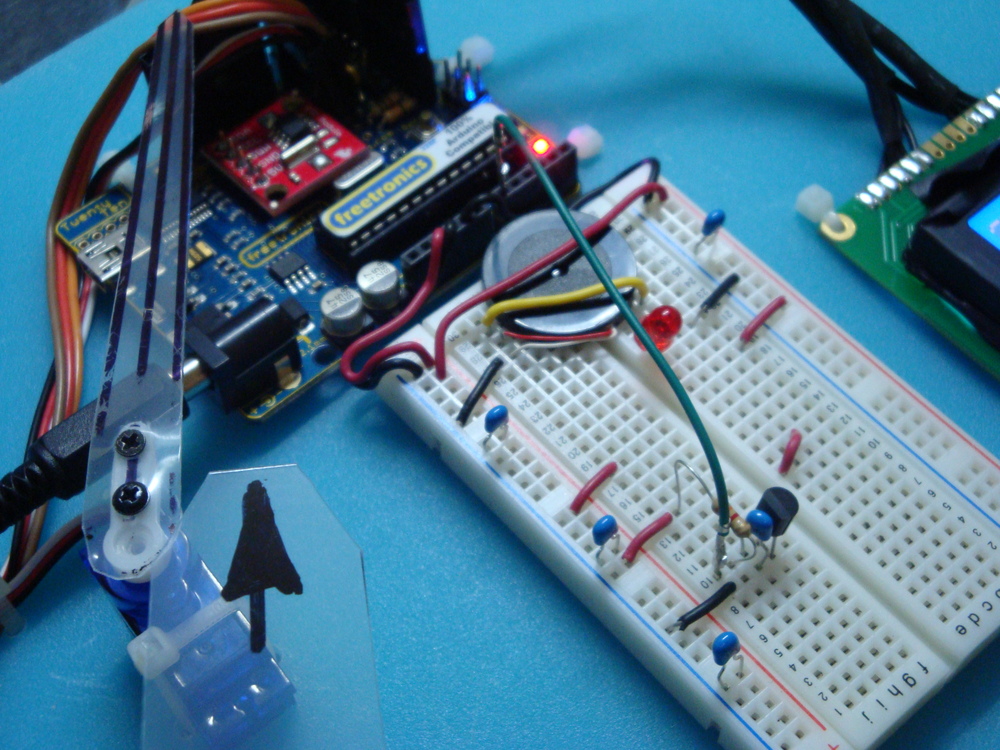
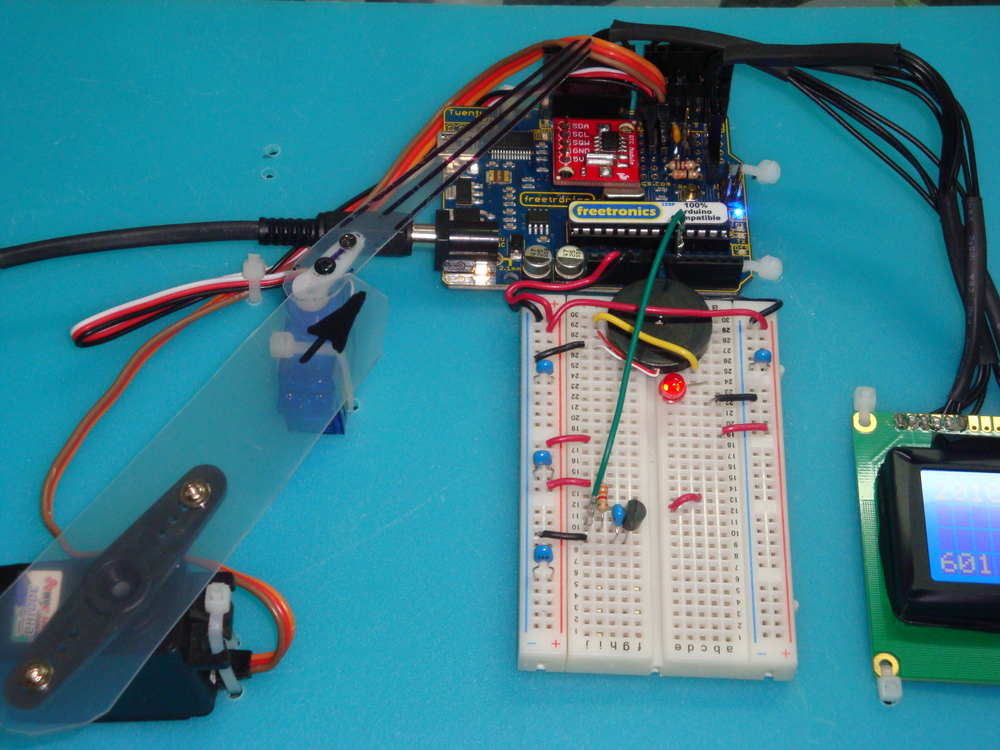
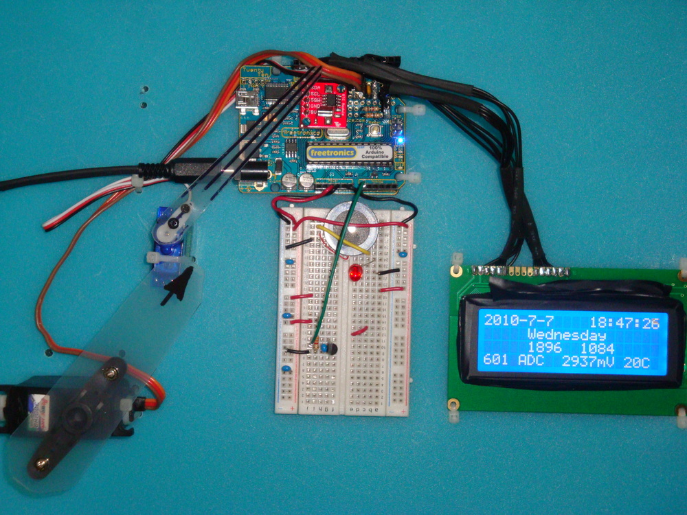
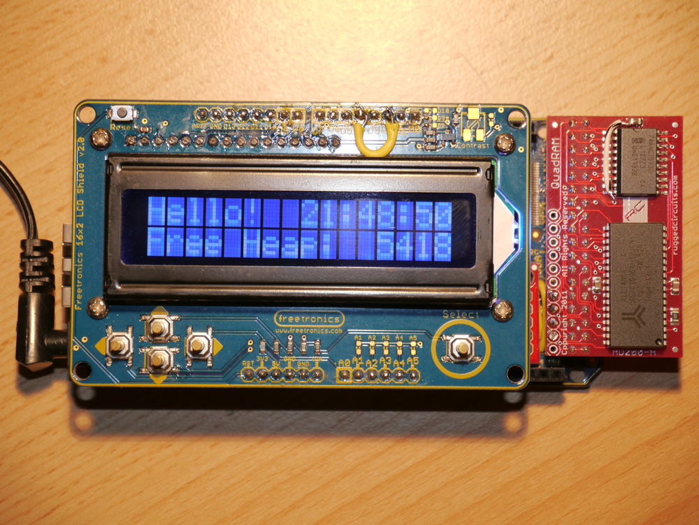
Recently, I also acquired a Freetronics 16×2 LCD-keypad-shield to use as a drop-on display for debugging and status, and anything really. It works really nicely and with its single pin switch analogue interface (which will be useful for navigation). Unfortunately there is a conflict between the SD Card device select pin on the EtherMega (Arduino pin D4) and one of the data pins on the 16×2 LCD.

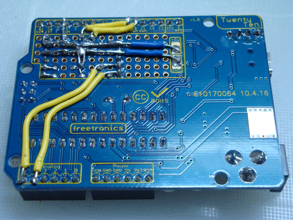
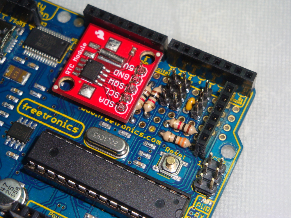
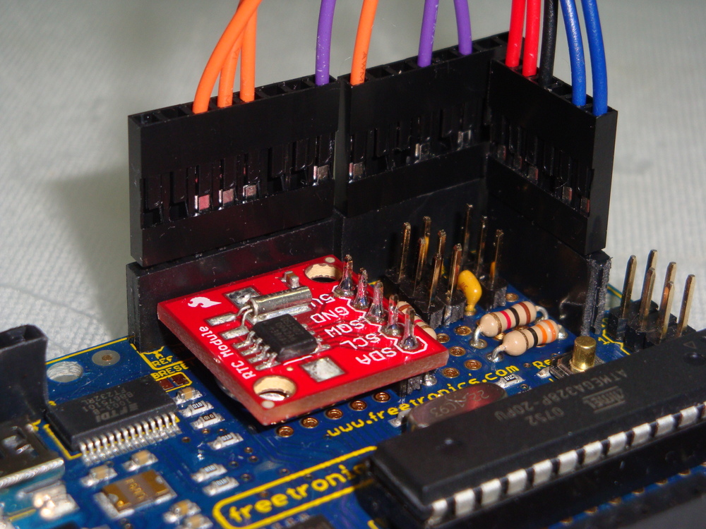
My rectification of this pin usage conflict can be seen on the pictures below, where the yellow wire joins Pin D4 to Pin D2. What can’t be seen is that the leg of Pin D4 has been cut off, so it doesn’t insert into the EtherMega, so there is no elecrical connection between the D4 pin on the 16×2 LCD, and the D4 Pin used on the EtherMega.

P1010882P1010884P1010883P1010886

Tools

Recently I purchased a Saleae Logic to use in developing. I have got to say that this is probably the best $149 that I have spent on any tool, ever. Having the ability to capture long periods (minutes) of data, with 24MHz resolution, and zoom, shrink, drag, flick around in it, and also compare many windows of alternative samples is just so great. It saves so much time being able to simply “see” what the device is actually doing on the SPI, I2C and serial ports, simultaneously, is well great. But I already said that.

P1010781

Software – FatF File System

As usual, the code is on AVRfreeRTOS on Sourceforge.

My main work was to put the existing ChaN’s FatFs Generic FAT File System Module v0.9 into my existing ATmega2560 freeRTOS system, using my existing libraries, and generally being fully integrated into the system, as a plaform for some further work.

This was fairly time consuming (until I got my Saleae Logic), because the SPI bus transfers required to initiate and drive a SD card are complex, and depend on which version of SD card (MMC, SD, HDSD) is being used.

Now that everything is working, I’ve also done some SPI optimisation, to speed up multi-byte SPI bus transfers used for reading and writing to the SD card.

In testing with a Freetronics EtherMega driving an 4GByte HDSD card the system achieved the following results.

  • Byte transfer cycle time: MOSI 3.750us, MISO 3.6250us
  • Multibyte transfer cycle time: MOSI 1.3333us, MISO 1.3750us
  • Gross Performance increase: MOSI 2.8x, MISO 2.64x

Measured performance for a multi-MegaByte file copy is about 140kBytes/s which includes both read and write operations to the same SD card.

Software – HD44780 LCD

As usual, the code is on AVRfreeRTOS on Sourceforge.

Also, as I had purchased a 16×2 LCD display and I wanted to implement a flexible solution for display, I also ported the Control Module for HD44780 Character LCD into my system.

This was pretty straightforward, once I’d recognised the pin confict issue between the two Freetronics devices, and perhaps the most interesting things to say are:

  • Using a macro to control the pin assignment means that it is very easy to change the pins used for any display type. Simply renumber them in the macro and it is done.
  • Also, using the standard avr-libc stdio utility vsprintf formatting allows me to choose how much library I want to bring in. The standard library doesn’t support float formatting, but with a simple link switch either a simpler (smaller) or more fully featured (larger) standard library can be included. I also use the standard avr-libc tools for the serial port, so there is no additional overhead specifically for the LCD.

Wiznet W5100

Now I’ve finished the W5100 drivers from Wiznet, incorporating their new v1.6 changes (because they screwed up the silicon ARP state machine). And also, a fix for a subtle bug caused
by writing to the W5100 Tx buffer before it was finished with a previous transmission. This was fixed by checking the Tx read pointer and comparing it with the Tx write pointer. When the chip is idle, they are the same. That took me 3 weeks to isolate.

Now the fun part starts, which will be to re-learn the IP protocol suites, through re-implementing some of the standard network tools, like HTTP, FTP, NTP, DHCP, DNS, that we just take for granted. DHCP is done. Ping is done. HTTP is done.

Here is a web server running on this platform.

EtherMega server

Freetronics freeRTOS Retrograde Real Time Clock (DS1307) – Part 2

Part 2 of this project involved learning how to use hardware PWM to control servos. And, then to make the clock actually work with retrograde analogue hands.

First the functional definition. A retrograde movement in horological terms is where the indicators or hands spring back to their home or 0 position at the end of their cycle. So for a minute hand, after 59 minutes and 59 seconds, its next movement would be to reverse move to home at 0 minutes. For the hour hand this could happen after 12 hours or 24 hours. 24 hours is the case that I have chosen to implement. The idea is to have the hour hand trace out a day from sunrise in the east, to vertical noon, and to set in the west.

In part 1, I added the servo headers to align with the Arduino Digital Pins 5 & 6. These pins are driven by the Timer 0 PWM hardware. Following quite a few evenings trying to understand how to generate PWM using the hardware (OK, I’m a bit slow), I realised that it is not very easy to get a good servo signal out of Timer 0 or Timer 2.

To generate the right signal for a servo, you need to produce a pulse every 20mS (50Hz). The width of the pulse should be 1.5mS to get the neutral position. Depending on the servo design, pulses with width from around 0.8mS to around 2.2mS (repeated every 20mS) will drive it to either end of its range. Depending on the servo, 0.8mS may drive it clockwise or anticlockwise. I have both in the clock. For example, the “hour” servo goes clockwise with a wider pulse. The “minute” servo is the reverse case.

The main issue with Timer 0 and Timer 2 is that they are 8 bit timers, counting to 255 before resetting to 0 (ideally after 20mS). Since the required pulses are between 0.8mS and 2.2mS, there are only about 12 “positions” available for the servo to take. Not enough to allow a minute hand to indicate 60 different positions.

Therefore it became clear that, for this application, it was only possible to use the 16 bit Timer 1 to control the servos.

Setting up Timer 1 is relatively easy, once that decision had been made, so the code was implemented. But, this meant that I had to reconnect the servo headers to Arduino Digital Pin 9 and Pin 10, which are driven by the Timer 1 PWM hardware.

Also, in the pictures below, I have added a header to allow power, LCD backlight (32Ohm), and contrast (1kOhm), connections to the standardised HD44780 LCD.

Dsc02787Dsc02791Dsc02789

Ok, so here’s the issue. I’m using the Pololu Libraries for writing to the LCD, and the standard connection for the data line 4 on the HD44780 LCD goes to Arduino Pin 9. The same pin I need for the Timer 1 PWM. Ouch.

Modifying the library is not too difficult. We can move the Data line attached to Pin 9 onto Pin 11, and all is well. This is done in the following file.

~/libpololu-avr/src/OrangutanLCD/OrangutanLCD.h

The changes are noted in the #define lines below

#define LCD_DB4                PORTB3        // Was PORTB1. Use PORTB3 to avoid the Timer1 pins.
#define LCD_DB5                PORTB4        // PB4
#define LCD_DB6                PORTB5        // PB5
#define LCD_DB7                PORTD7        // PD7

//    PortB:     7 6 5 4 3 2 1 0
//  LCD Data:      2 1 0            Use DB3 to avoid Timer1 pins.
//  LCD Data:      2 1     0
//
//  PortD:     7 6 5 4 3 2 1 0
//  LCD Data:  3

#define LCD_PORTB_MASK            ((1 << LCD_DB4) | (1 << LCD_DB5) | (1 << LCD_DB6))  // Modified to avoid using DB1
#define LCD_PORTD_MASK            (1 << LCD_DB7)
#define LCD_PORTB_DATA(data)    ((data & 0x07) << 3)  // Modified the data mask to avoid using DB1
#define LCD_PORTD_DATA(data)    ((data & 0x08) << 4)

The below pictures show the LCD pin layout.
<blockquote”>Red = VCC

Black = GND

BLUE = Voltage for contrast or backlight

Orange = Data lines (4-bit: DB4 – DB7) PB3 (not PB1), PB4, PB5, and PD7. Arduino Digital pins 11 (not 9), 12, 13, and 7

Purple = Control lines (RS, R/W, E) PD2, PB0, and PD4. Arduino Digital pins 2, 8, and 4

Dsc02793Dsc02796

So now we have PWM for our retrograde analogue hands, and a LCD display.

But wait, there’s more…

There’s too much display going to waste, so let’s add something else… Hmm… Temperature, and time, make a min/max thermometer that can show what time each extreme temperature was reached during the day.

Quickly getting a LM335Z temperature sensor, I’m now testing whether the 10bit ADC is good enough to generate reasonable temperature readings from the device. At full range of 5000mV across 1024 levels, we have about 4.88mV per level. The LM355Z produces 10mV per degree, so we should be able to get 0.5 degree accuracy. If everything is perfect.

Currently the temperature gauge works, but the accuracy is still a work in progress, as are the min / max functions. The LM335Z has only two connections, and is biased by a single resistor (3200 Ohm), so it will fit into the board if that is all that is needed. Getting perfection may require addition of decoupling capacitors on AREF and across the sensor, but I’m still
experimenting with this.

Dsc02838Dsc02839

The overall working product is shown below. But wait, there’s more…

I was not happy with using resistors to tie up the SCL and SDA lines high for the I2C bus, as it should be possible to use the internal pull up resistors in some situations (according to the Atmel datasheet).

So using a new Freetronics 2010 from Little Bird Electronics, the clock is now rebuilt without external pull up resistors. The I2C code is modified to only pull up the lines between the start and stop bus instructions. The levels are messy (not showing sharp transitions in my SLO) but, never the less the code and the clock works.

The working device is shown below. Note the rather funky white on blue display I got from Sparkfun.

Dsc02842

In the years since this instruction was writen, I’ve migrated to Github. So the code is hosted here. The freeRTOS code is also posted on Github. I used the Pololu Library for writing to the display, so it needs to be installed along with the normal AVR libraries.

Part 3 will look at how to build a really stylish clock face that can be shown off in public