My Gameduino 2 was delivered just a few weeks ago, and I’ve spent too much time with it already. It is the latest Kickstarter project by James Bowman. James has written a Gameduino 2 Book too.
Sourcecode for the below examples is located at GitHub AVRfreeRTOS lib_ft800 and the application is located at GA_Synth.
Recently, I’ve used the Gameduino 2 together with the Goldilocks Analogue to implement a multi-oscillator audio synthesizer GUI, using many FTDI EVE GPU co-processor widgets. The use of widgets linked with the integrated touch functionality really simplifies the programming of complex GUIs.
The ability to add a large touch screen, with integrated audio and accelerometer to any Arduino project is a great thing. Previously, you had to move to 32 bit processors with LVDS interfaces to work with LCD screens, but the new FT800 EVE Graphical Processing Unit (GPU) integrates all of the graphic issues and allow you to drive it with a very high level object orientated graphics language. For example it takes just one command to create an entire clock face with hour, minute, and second-hands.
The Gameduino 2, via the FT800 EVE chip, provides the following capabilities:
- 32-bit internal color precision
- OpenGL-style command set
- 256 KBytes of video RAM
- smooth sprite rotate and zoom with bilinear filtering
- smooth circle and line drawing in hardware – 16x antialiased
- JPEG loading in hardware
- audio tones and WAV audio output
- built-in rendering of gradients, text, dials, sliders, clocks and buttons
- intelligent touch capabilities, where objects can be tagged and recognised.
The FT800 runs the 4.3 inch 480×272 TFT touch panel screen at 60 Hz and drives a mono headphone output.

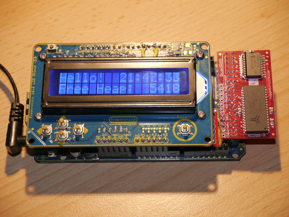
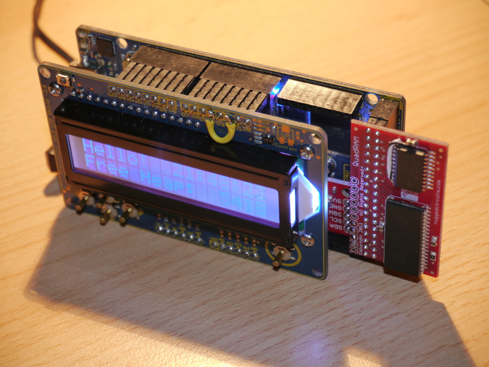
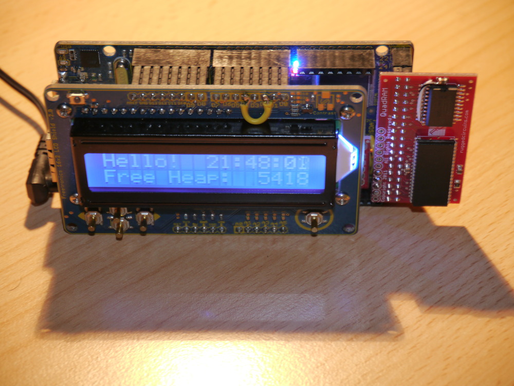
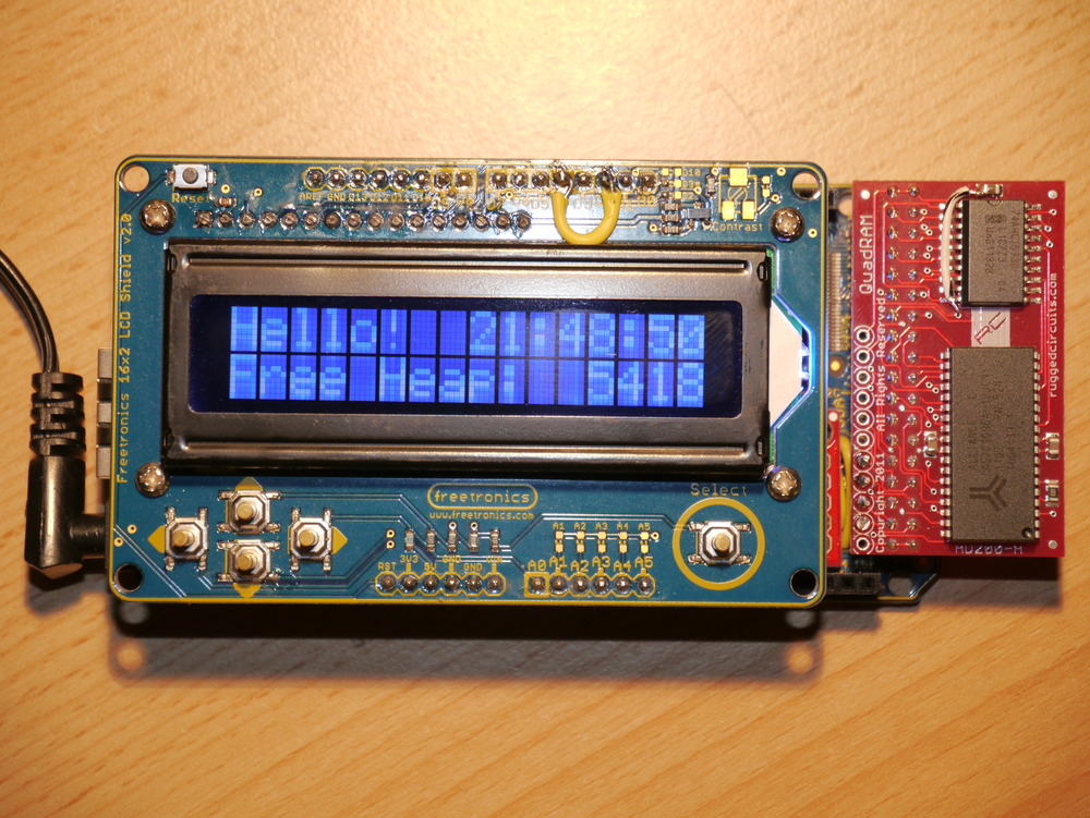
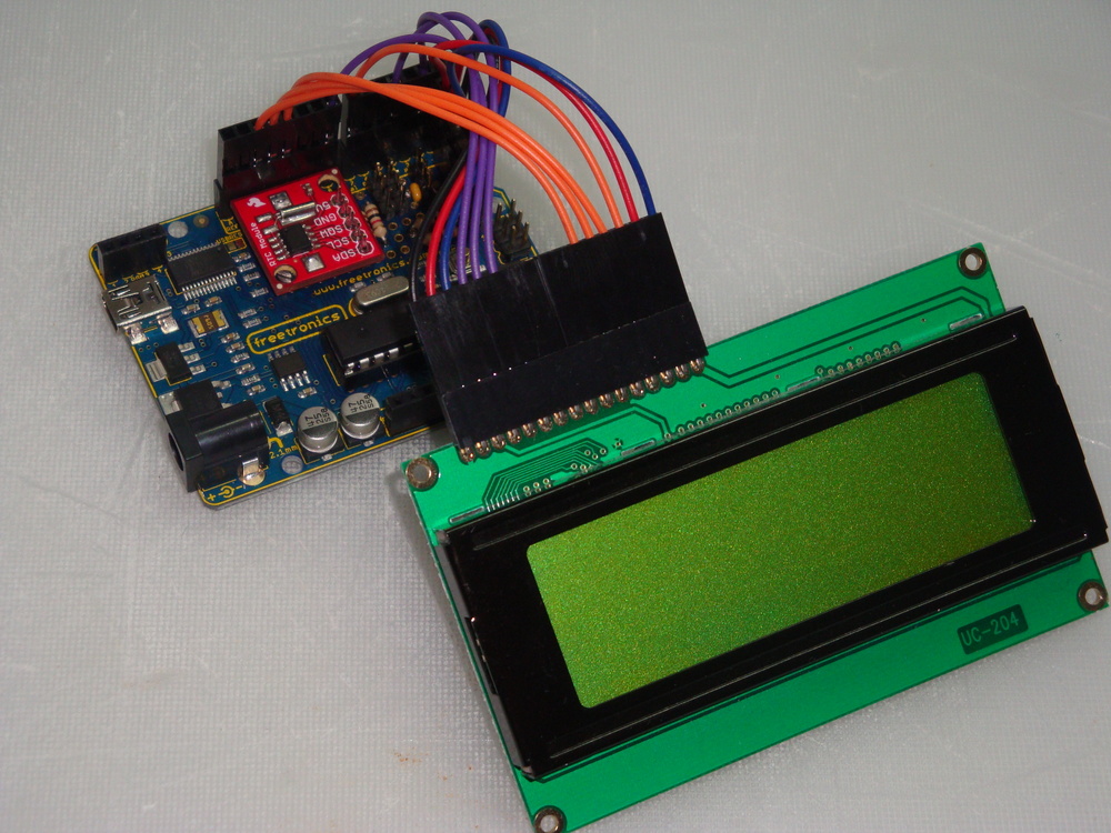
First off, there’s a demo of some of the capabilities of the Gameduino 2. I’ll come to the drivers later, but the Arduino compatible platform used here is the Goldilocks ATmega1284P from Freetronics. The Goldilocks is in my opinion the best platform to use with the Gameduino 2. Firstly there is the extra RAM and Flash capabilities in line with the ATmega1284p MCU. But also importantly the Goldilocks holds the Pre-R3 Arduino Uno connector standard, with the SPI pins located correctly on Pins 11, 12, and 13. And the INT0 interrupt located on Pin 2. This means that it can be used with the Gameduino 2, out of the box. No hacking required.
The Goldilocks Analogue is an upgraded replacement for the original Goldilocks, with many additional features. Thank you for pledging on the Goldilocks Analogue Kickstarter Project page, which was successfully closed on November 19th 2015, with 124% funding. Now that the Kickstarter pledges have been shipped, the new Goldilocks Analogue is now available on Tindie.


Must be addicted to these touch screens. I’ve just received an Australian designed 4D Systems FT843 Screen. It has possibly an identical screen to the Gameduino 2, but is based on a R3 Arduino shield format (SPI on ICSP) called the ADAM (Arduino Display Adapter Module), which means that it will work on any current Arduino hardware, without hacking. The FT843 ADAM supports a RESET line, which resolves the only problem I’ve noted with the Gameduino 2. Unfortunately, audio is not supported by a 3.5mm jack but rather by a pin-out option. The FT843 uses Swizzle 0, unlike the Gameduino 2 which uses Swizzle 3, and has the Display SPI Select on either D9 or D4 rather than on D8 like the Gameduino 2. Other than these simple configuration options, it similar.
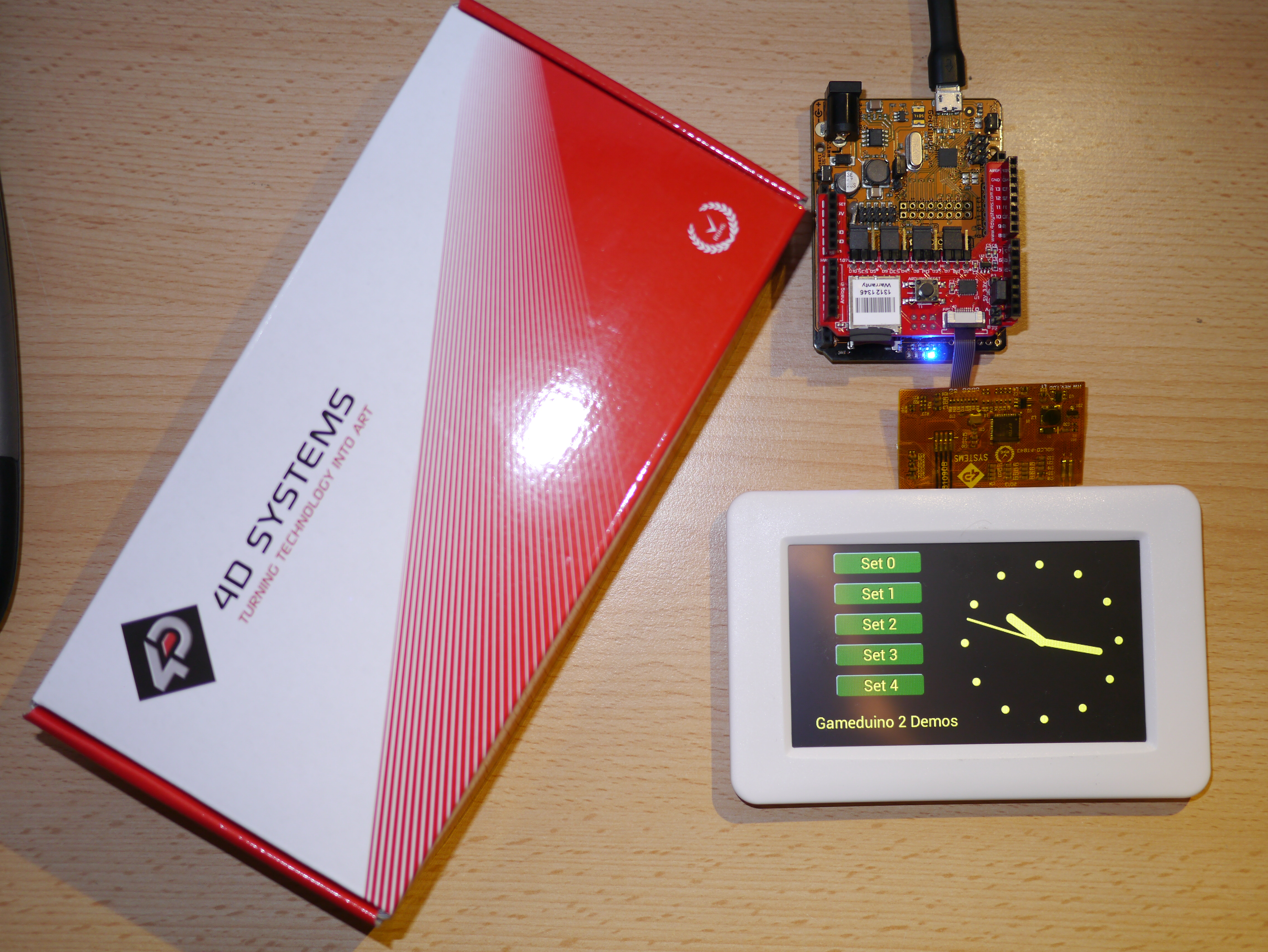
4D Systems FT843 on Goldilocks 1284p
Demo
The screen shows 5 sets of demonstrations. These demos are provided by FTDI, and typically in an Arduino Uno you would have to choose which of the 5 sets you want to see. With the extra capabilities of the Goldilocks, it is possible to load all of them simultaneously in 110kB of flash.
Set 0 focusses on individual commands that are loaded into the Display List. The Display List is essentially a list of commands that is executed or rendered for each frame of display. A Display List will be rendered indefinitely, until it is swapped by another Display List. Two Display Lists are maintained in a double buffering arrangement. One is written, whilst the other is displayed.
Set 1 exhibits some of the co-processor command capabilities, that allow complex objects to be created with only one command. A clock, slider, dial, or a rows of buttons can be created easily in this manner.
Set 2 shows the JPEG image rendering capabilities in RGB and in 8 bit mono.
Set 3 demonstrates custom font capabilities. There are 16 fonts available in the ROM of the FT800 EVE, but you can add your own as is desired.
Set 4 shows some advanced co-processor capabilities, such as touch tag recognition, no touch (zero MCU activity) screensaver, capturing screen sketches, and inbuilt audio options.
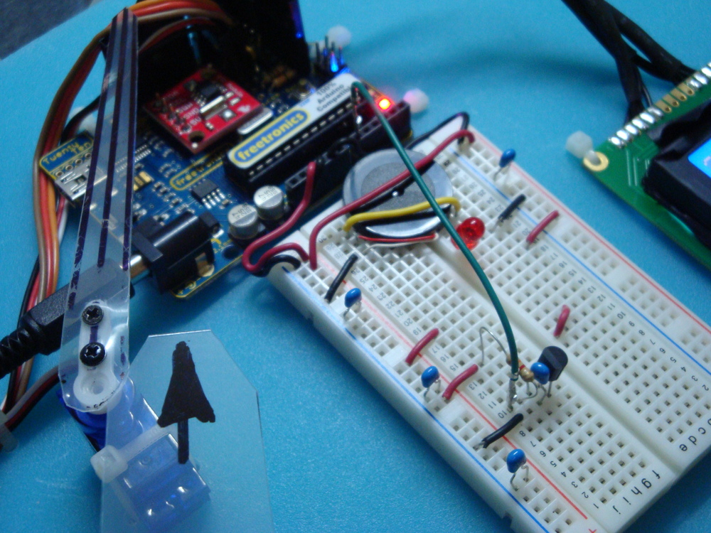
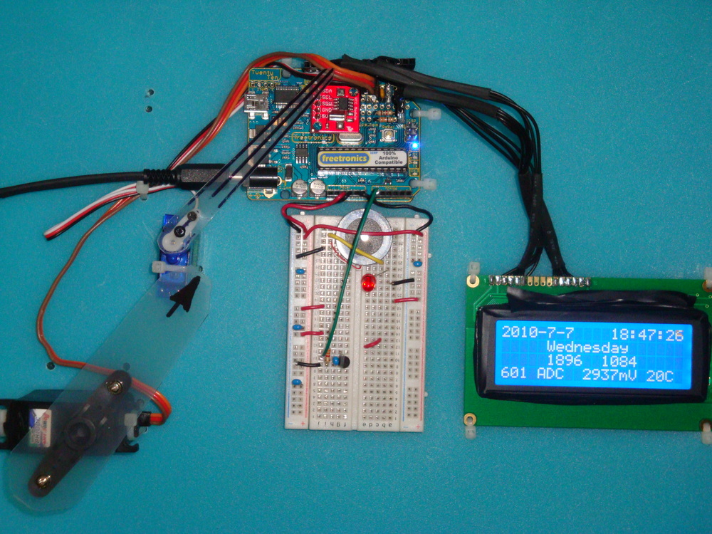
The main screen shows an analogue clock that is drawn with one co-processor command. Real time is generated by a 32,768Hz Crystal driving the Goldilocks Timer 2 for a system clock. The accuracy of the clock is limited only by the accuracy of the watch crystal, and I’ve built mine with a 5ppm version, which should be enough to keep within a few seconds per month.
Sample Application
The FTDI provided sample application covers most of the available commands and options for the FT800 EVE GPU.
The FT_SampleApp.h file contains definitions of functions implemented for the main application. These code snippets are not really useful beyond demonstrations of capability of the GPU, but never the less demonstrate how each specific feature of the FT800 EVE GPU can be utilised.
Driver
Because the FT800 EVE GPU has a very capable object orientated graphics language, the FTDI drivers present a very capable high level interface to the user. FTDI have prepared an excellent starting point from which I could easily make customisations suitable for the AVR ATmega Arduino hardware that I prefer to use.
The FTDI driver set is separated into a Command Layer, and into a Hardware Abstraction Layer (HAL). This separation makes it easy to customise for the AVR ATmega platform, but retains the standard FTDI command language for easy implementation of their example applications, and portability of code written for their command language.
To use the FT800 EVE drivers for the Gameduino 2 it is only necessary to include the FT_Platform.h file in the main program. This file contains references to all of the other files needed.
#include "../lib_ft800/FT_DataTypes.h"
#include "../lib_ft800/FT_X11_RGB.h"
#include "../lib_ft800/FT_Gpu.h"
#include "../lib_ft800/FT_Gpu_Hal.h"
#include "../lib_ft800/FT_Hal_Utils.h"
#include "../lib_ft800/FT_CoPro_Cmds.h"
#include "../lib_ft800/FT_API.h"
The FT_DataTypes.h file contains FTDI type definitions for the specific data types needed for the FT800 EVE GPU. This is mainly used to abstract the drivers for varying MCU. For the AVR it is not absolutely necessary, but it will help when the code is used on other platforms.
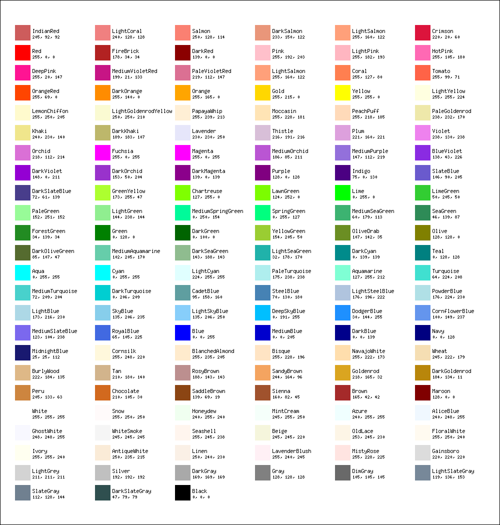
The FT_X11_RGB.h file contains the standard colour set used in X11 colours and on the Web, which are stored PROGMEM. I’ve written a small macro that will insert these into commands needing 24 bit colour settings. These colours will be stored and referenced from PROGMEM when they are called from either of the X11 specific macros defined in FT_Gpu.h If they are not called from the program, they will be discarded by the linker and not waste space in the final linked program.
The FT_Gpu.h file contains all the definitions for command and register setting options. I have significantly rearranged the layout and comments in this file, compared to the FTDI version. Hopefully it is arranged in a way that allows options applying to specific commands and registers to be quickly located.
By writing DL commands to the Display List which are configured by the options in the FT_Gpu.h file it is possible to control most of the low level functions in the FT800 EVE GPU. The Display List is used by the FT800 GPU to render the screen, so it is only the contents of the active Display List that appear on the screen.
In the FT_Gpu_Hal.h file the commands specific to the SPI bus (or the I2C bus if this transfer mechanism is being used) are defined.
I have simplified out some HAL options provided by FTDI for high performance MCU, that might be constrained writing to the SPI bus at only 30MHz, the maximum FT800 SPI bus rate. The Goldilocks SPI bus only runs at 11MHz, and the standard Arduino Uno SPI bus only runs at 8 MHz, so those optimisations don’t help, and they also consume RAM for streaming buffers.
But, I have integrated a multi-byte SPI transfer into the HAL, which don’t use additional RAM buffer space, as they write via a pointer. This is probably the best way to work the SPI bus in the Arduino environment. I have also implemented multi byte SPI transfer directly from the PROGMEM for Strings, and for precomputed commands.
As a preferred option, I’ve implemented PROGMEM storage of Strings for all commands. The commands utilising RAM storage of Strings are retained for compatibility, and to allow computed Strings to be used.
All of the FTDI provided commands now have optional *_P variants which take PROGMEM strings, rather than RAM strings. This saves eleven hundred bytes of RAM used for strings, just in the demonstration programs provided by FTDI and shown in the Demo!
The FT_Hal_Util.h file contains some simple utility macros.
The FT_CoPro_Cmds.h file contains definitions for all of the available co-processor commands. These command are written to the co-processor command buffer, and are used to generate low level commands that appear in the Display List and be rendered for each frame.
Many of the co-processor commands replicate functionality of setting specific registers with options via the Display List GPU commands. This is useful because it is possible to programme the co-processor to implement a task and remain at the object orientated view of the screen, even though the a individual command may be a simple GPU setting that could have been done at Display List command level. Having all the commands available at co-processor level obviates the need to switch between the two “modes” of operation and thought.
I extracted a few of the standard functions that are needed irrespective of the specific application into an API. The FT_API.h file contains these simple command sequences, for booting up the Gameduino 2, and for managing the screen brightness. It also contains precalculated simplified sin, cos, and atan functions useful when drawing circles and clocks.
The API level also contains calls on the Hardware Abstraction Layer that are simply passed through. These calls are flattened by avr-gcc to save digging ourselves into a stack wasting function call hole.
And, of course, everything is integrated into the freeRTOS v8.0.0 port that I support on Sourceforge, AVRfreeRTOS, which gives non-blocking timing, tasks, semaphores, queues, and all aspects of freeRTOS that are so great.
As an example of the power of this combination of freeRTOS and the FT800 object orientated command language we can describe the method used to create an accurate well rendered clock on the Gameduino 2 screen. Using the 3 commands below, we obtain the clock face seen in my demo video main screen.
time(¤tTime); // get a time stamp in current seconds elapsed from Midnight, Jan 1 2000 UTC (the Y2K 'epoch'), as maintained by freeRTOS. localtime_r(¤tTime, &calendar); // converts the time stamp pointed to by currentTime into broken-down time in a calendar structure, expressed as Local time. FT_GPU_CoCmd_Clock(phost, FT_DispWidth - (FT_DispHeight/2), FT_DispHeight/2, FT_DispHeight/2 - 20, OPT_3D, calendar.tm_hour, calendar.tm_min, calendar.tm_sec, 0); // draw a clock in 3D rendering.
I’ve updated the clock function to include a touch screen time setting interface. Using the FT800 Touch Tags, and Button generation, this process is really incredibly easy.
Hardware
I’ve taken the liberty of borrowing some of James’ pictures for this story. They can originally be found here.

Note that because of the wrap around connector and cable for the LCD screen, it is not possible to use the Arduino R3 pin out. The SPI bus pins are located at the traditional location on Pin 11 though Pin 13. Unless you want to hack your board, you’re limited to using Arduino Uno style boards.

Unfortunately, the FTDI FT800 Reset pin has not been implemented by the Gameduino 2. Using an ISP to programme the Arduino usually “accidentally” puts the FT800 EVE GPU into an unsupported state. This means that the Gameduino 2 and Arduino usually have to be power-cycled or hard Reset following each programming iteration. It would have been good to tie the FT800 Reset pin to the Arduino Reset pin via a short (ms) delay chip, to obviate the need to remove power to generate the hard Reset for the FT800.
Hello World & other examples
I thought it might be interesting to compare the code required to achieve the demonstration outcomes that James Bowman provides on the Gameduino2 site, with the code required to achieve the same result using freeRTOS and the FTDI style driver. So I’ve implemented three simple examples, “Hello World”, “Sprites”, and “Blobs” from his library.
All of the examples have been built using an Arduino Uno ATmega328p as the MCU hardware platform.

The Hello World application simply initialises the Gameduino2, sets the colour to which the screen shall be cleared, and then writes text with the OPT_CENTER option to center it in the X and Y axis. As there is no delay, this is written as often and as fast as the MCU can repeat the loop.
#include
#include

void setup()
{
  GD.begin();
}

void loop()
{
  GD.ClearColorRGB(0x103000);
  GD.Clear();
  GD.cmd_text(240, 136, 31, OPT_CENTER, "Hello world");
  GD.swap();
}
The same result can be generated in C using freeRTOS and the FTDI Drivers. I have commented extensively within the code below.
/* freeRTOS Scheduler include files. */
/* these four header files encompass the full freeRTOS real-time OS features,
   of multiple prioritised tasks each with their own stack space, queues for moving data,
   and scheduling tasks, and semaphores for controlling execution flows */
#include "FreeRTOS.h"
#include "task.h"
#include "queue.h"
#include "semphr.h"

/* Gameduino 2 include file. */
#include "FT_Platform.h"

/*------Global used for HAL context management---------*/
extern FT_GPU_HAL_Context_t * phost;           // optional, just to make it clear where this variable comes from.
                                               // It is automatically included, so this line is actually unnecessary.

/*--------------Function Definitions-------------------*/

int main(void) __attribute__((OS_main));       // optional, just good practice.
                                               // Saves a few bytes of stack because the return from main() is not implemented.

static void TaskWriteLCD(void *pvParameters);  // define a single task to write to Gameduino 2 LCD.
                                               // typically multiple concurrent tasks are defined,
                                               // but in this case to replicate the Arduino environment, just one is implemented.

/*-----------------Functions---------------------------*/
/* Main program loop */
int main(void)
{
  xTaskCreate(            // create a task to write on the Gameduino 2 LCD
       TaskWriteLCD
    ,  (const portCHAR *)"WriteLCD"
    ,  128                // number of bytes for this task stack
    ,  NULL
    ,  3		  // priority of this task (1 is highest priority, 4 lowest).
    ,  NULL );

  vTaskStartScheduler();  // now freeRTOS has taken over, and the pre-emptive scheduler is running.
}
/*-----------------------------------------------------------*/
/* Tasks                                                     */
/*-----------------------------------------------------------*/

static void TaskWriteLCD(void *pvParameters) // A Task to write to Gameduino 2 LCD
{
  (void) pvParameters;

  FT_API_Boot_Config();  // initialise the Gameduino 2.

  while(1)               // a freeRTOS task should never return
  {
    FT_API_Write_CoCmd( CMD_DLSTART );                       // initialise and start a Display List
//  FT_API_Write_CoCmd( CLEAR_COLOR_RGB(0x10, 0x30, 0x00) ); // set the colour to which the screen is cleared (using RGB triplets) as in GD2 library OR
    FT_API_Write_CoCmd( CLEAR_COLOR_X11(FORESTGREEN) );      // set the colour to which the screen is cleared (using X11 colour definitions)
    FT_API_Write_CoCmd( CLEAR(1,1,1) );                      // clear the screen

    FT_GPU_CoCmd_Text_P(phost,FT_DispWidth/2, FT_DispHeight/2, 31, OPT_CENTER, PSTR("Hello world"));
      // write "Hello World" to X and Y centre of screen using OPT_CENTER  with the largest font 31
      // The string "Hello world" is stored in PROGMEM
      // Functions with *_P all use PROGMEM Strings (and don't consume RAM)
      // FT_DispWidth and FT_DispHeight are global variables set to orientate us in a flexible consistent way,
      // without hard coding the screen resolution.

    FT_API_Write_CoCmd( DISPLAY() );                         // close the Display List (DL) opened by CMD_DLSTART()
    FT_API_Write_CoCmd( CMD_SWAP );                          // swap the active Display List (double buffering), to display the new "Hello World" commands written to the Display List
  }
}
![]()
The Sprites application is similar to the original one built for the Gameduino, but here each sprite is rotating around a random point. The 2001 random points are stored in a PROGMEM array sprites. This takes 8K of flash. A second PROGMEM array circle holds the 256 XY coordinates to make the sprite move in a circle. The only RAM used is a single byte t used to keep track of the current rotation position, by counting iterations.
#include
#include
#include

#include "sprites_assets.h"

void setup()
{
  GD.begin();
  GD.copy(sprites_assets, sizeof(sprites_assets));
}

static byte t;

void loop()
{
  GD.Clear();
  GD.Begin(BITMAPS);
  byte j = t;
  uint32_t v, r;

  int nspr = min(2001, max(256, 19 * t));

  PROGMEM prog_uint32_t *pv = sprites;
  for (int i = 0; i < nspr; i++) {
    v = pgm_read_dword(pv++);
    r = pgm_read_dword(circle + j++);
    GD.cmd32(v + r);
  }

  GD.ColorRGB(0x000000);
  GD.ColorA(140);
  GD.LineWidth(28 * 16);
  GD.Begin(LINES);
  GD.Vertex2ii(240 - 110, 136, 0, 0);
  GD.Vertex2ii(240 + 110, 136, 0, 0);

  GD.RestoreContext();

  GD.cmd_number(215, 110, 31, OPT_RIGHTX, nspr);
  GD.cmd_text( 229, 110, 31, 0, "sprites");

  GD.swap();
  t++;
}
The code in freeRTOS is similar. I have commented within the code.
/* freeRTOS Scheduler include files. */
#include "FreeRTOS.h"
#include "task.h"
#include "queue.h"
#include "semphr.h"

/* Gameduino 2 include file. */
#include "FT_Platform.h"

// The include file containing the sprite graphics, and the special command sequence
#include "sprites_assets.h

/*------Global used for HAL context management---------*/
extern FT_GPU_HAL_Context_t * phost;           // optional, just to make it clear where this variable comes from

/*--------------Function Definitions-------------------*/

int main(void) __attribute__((OS_main));       // optional, just good practice

static void TaskWriteLCD(void *pvParameters);  // define a single task to write to Gameduino 2 LCD

/*-----------------Functions---------------------------*/

/* Main program loop */
int main(void)
{
  xTaskCreate(             // create a task to write on the Gameduino 2 LCD
    TaskWriteLCD
    ,  (const portCHAR *)"WriteLCD"
    ,  128                 // number of bytes for this task stack
    ,  NULL
    ,  3                   // priority of task (1 is highest priority, 4 lowest).
    ,  NULL );

  vTaskStartScheduler();   // now freeRTOS has taken over, and the pre-emptive scheduler is running
}
/*-----------------------------------------------------------*/
/* Tasks                                                     */
/*-----------------------------------------------------------*/

static void TaskWriteLCD(void *pvParameters) // A Task to write to Gameduino 2 LCD
{
  (void) pvParameters;

  uint8_t t = 0;         // iterate over the code for 255 times, before restarting with 256 sprites where t = 0

  FT_API_Boot_Config();  // initialise the Gameduino 2.
  FT_GPU_HAL_WrCmdBuf_P(phost, sprites_assets, sizeof(sprites_assets));
    // Copy James' magic list of commands into the command buffer.
    // These co-processor commands are "compiled" into their 4 byte equivalents, and I haven't decoded them in detail.
    // But, since the FT800 is reading the same double word codes, it doesn't really matter how they're generated.

  while(1)               // a freeRTOS task should never return
  {
    FT_API_Write_CoCmd( CMD_DLSTART );       // initialise and start a Display List (DL)
    FT_API_Write_CoCmd( CLEAR(1,1,1) );      // clear the screen

    FT_API_Write_CoCmd( BEGIN(BITMAPS) );    // start to write BITMAPS into the DL
    uint8_t j = t;
    uint32_t v;
    uint32_t r;
    int16_t nspr = min(2001, max(256, 19 * t));
    ft_prog_uint32_t * pv = sprites;         //  pv is the sprite BITMAP pointer

    for (uint16_t i = 0; i < nspr; ++i) {
      v = pgm_read_dword(pv++);              // determine which sprite we're controlling
      r = pgm_read_dword(circle + j++);      // circle is the rotation control
      FT_GPU_HAL_WrCmd32(phost, v + r);      // the sprite address and the location are written here to the co-processor
    }
    FT_API_Write_CoCmd( END());              // finish writing BITMAPS into the Display List

    FT_API_Write_CoCmd( BEGIN(LINES) );      // start to write LINES into the Display List
    FT_API_Write_CoCmd( COLOR_RGB(0x00, 0x00, 0x00) );  // set the line colour to black 0x000000
    FT_API_Write_CoCmd( COLOR_A(140) );                 // set alpha channel transparency
    FT_API_Write_CoCmd( LINE_WIDTH( 28 * 16) );
    FT_API_Write_CoCmd( VERTEX2II(240 - 110, 136, 0, 0) );  // start to draw an alpha transparency background line
    FT_API_Write_CoCmd( VERTEX2II(240 + 110, 136, 0, 0) );  // finish the line
    FT_API_Write_CoCmd( END() );             // finish writing LINES into the Display List

    FT_API_Write_CoCmd( RESTORE_CONTEXT() ); // With no prior SAVE_CONTEXT() command, this restores the default colours and values.

    FT_GPU_CoCmd_Number(phost, 215, 110, 31, OPT_RIGHTX, nspr);    // write a number.
    FT_GPU_CoCmd_Text_P(phost, 229, 110, 31, 0, PSTR("sprites"));  // write using a PROGMEM stored string function, to save RAM
      //  phost is a pointer to the context for the Gameduino2.
      //  Mainly used where there may be multiple screens present, but in this case several state and semaphore items are maintained.

    FT_API_Write_CoCmd( DISPLAY() );          // close the active Display List (DL) opened by CMD_DLSTART()
    FT_API_Write_CoCmd( CMD_SWAP );           // Do a DL swap to render the just written DL

    t++;    // t will roll over and will restart the number of sprites to the minimum of 256
  }
}

blobs is a sketching demonstration, as you paint on the touch screen a trail of circles follows.
The code keeps a history of the last 128 touch positions, and draws the transparent, randomly coloured circles.
#include
#include
#include

#define NBLOBS      128
#define OFFSCREEN   -16384

struct xy {
  int x, y;
} blobs[NBLOBS];

void setup()
{
  GD.begin();

  for (int i = 0; i < NBLOBS; i++) {
    blobs[i].x = OFFSCREEN;
    blobs[i].y = OFFSCREEN;
  }
}

void loop()
{
  static byte blob_i;
  GD.get_inputs();
  if (GD.inputs.x != -32768) {
    blobs[blob_i].x = GD.inputs.x << 4;
    blobs[blob_i].y = GD.inputs.y << 4;
  } else {
    blobs[blob_i].x = OFFSCREEN;
    blobs[blob_i].y = OFFSCREEN;
  }
  blob_i = (blob_i + 1) & (NBLOBS - 1);

  GD.ClearColorRGB(0xe0e0e0);
  GD.Clear();

  GD.Begin(POINTS);
  for (int i = 0; i < NBLOBS; i++) {
    // Blobs fade away and swell as they age
    GD.ColorA(i << 1);
    GD.PointSize((1024 + 16) - (i << 3));

    // Random color for each blob, keyed from (blob_i + i)
    uint8_t j = (blob_i + i) & (NBLOBS - 1);
    byte r = j * 17;
    byte g = j * 23;
    byte b = j * 147;
    GD.ColorRGB(r, g, b);

    // Draw it!
    GD.Vertex2f(blobs[j].x, blobs[j].y);
  }
  GD.swap();
}
The code in freeRTOS is similar, but the touch functionality is derived directly from the FT800 register containing the most recent screen touch location. I have commented within the code.
/* freeRTOS Scheduler include files. */
#include "FreeRTOS.h"
#include "task.h"
#include "queue.h"
#include "semphr.h"
/* Gameduino 2 include file. */
#include "FT_Platform.h"
#define NBLOBS 128
#define OFFSCREEN -16384
/*———-Global used for HAL management————-*/
extern FT_GPU_HAL_Context_t * phost; // optional, just to make it clear where this comes from
struct xy { // somewhere to store all the blob locations
int16_t x, y;
} blobs[NBLOBS];
/*————–Function Definitions——————-*/
int main(void) __attribute__((OS_main)); // optional, just good practice
static void TaskWriteLCD(void *pvParameters); // define a single task to write to Gameduino 2 LCD
/*—————–Functions—————————*/
/* Main program loop */
int main(void)
{
xTaskCreate( // create a task to write on the Gameduino 2 LCD
TaskWriteLCD
, (const portCHAR *)"WriteLCD"
, 128 // number of bytes for the task stack
, NULL
, 3 // priority of task (1 is highest priority, 4 lowest).
, NULL );
vTaskStartScheduler(); // now freeRTOS has taken over, and the scheduler is running
}
/*———————————————————–*/
/* Tasks */
/*———————————————————–*/
static void TaskWriteLCD(void *pvParameters) // A Task to write to Gameduino 2 LCD
{
(void) pvParameters;
FT_API_Boot_Config(); // initialise the Gameduino 2.
FT_API_Touch_Config(); // initialise the FT800 Touch capability.
for (uint8_t i = 0; i > 16) & 0xffff) << 4; // read where x axis touch occurred, and scale it
blobs[blob_i].y = (int16_t)(readTouch & 0xffff) << 4; // read where y axis touch occurred, and scale it
} else {
blobs[blob_i].x = OFFSCREEN; // if there was no touch, draw the blob OFFSCREEN
blobs[blob_i].y = OFFSCREEN;
}
blob_i = (blob_i + 1) & (NBLOBS – 1); // increment to the next blob for touch interaction
// this is the display interface stuff
FT_API_Write_CoCmd( CMD_DLSTART ); // initialise and start a display list (DL)
FT_API_Write_CoCmd( CLEAR_COLOR_RGB(0xe0, 0xe0, 0xe0) );// set the colour to which the screen will be cleared
FT_API_Write_CoCmd( CLEAR(1,1,1) ); // clear the screen
FT_API_Write_CoCmd( BEGIN(POINTS) ); // start to write POINTS into the Display List (DL)
for (uint8_t i = 0; i < NBLOBS; ++i)
{
// Blobs fade away and swell as they age
FT_API_Write_CoCmd( COLOR_A(i << 1) ); // set an alpha transparency
FT_API_Write_CoCmd( POINT_SIZE((1024 + 16) – (i << 3)) );
// Random colour for each blob, keyed from (blob_i + i)
uint8_t j = (blob_i + i) & (NBLOBS – 1);
uint8_t r = j * 17;
uint8_t g = j * 23;
uint8_t b = j * 147;
FT_API_Write_CoCmd( COLOR_RGB(r, g, b) );
// Draw it!
FT_API_Write_CoCmd( VERTEX2F(blobs[j].x, blobs[j].y) );
}
FT_API_Write_CoCmd( END() ); // finish writing POINTS into the active DL
FT_API_Write_CoCmd( DISPLAY() ); // close the active Display List (DL)
FT_API_Write_CoCmd( CMD_SWAP ); // Do a DL swap to render the just written DL
}
}
I intend to build a few more demonstrations of the code, and to copy some games that James has already implemented, because I'm not a game designer.