
I was pondering the blank space on my 2010 recently, and combining that space with some other left over kit from Dogbot, I decided to make a dual retrograde analogue clock.
To build the clock I have the choice of either using NTP to sync a wireless enabled device, or use a RTC clock and re-set it every month or so. For this iteration, I’ve decided to go the RTC route.
Actually, reading this Tronixstuff page also got me going on the idea of using a DS1307 chip, and also Sparkfun makes a nice module that just happens to fit in the vacant space on the 2010. So, I bought one from LittleBird Electronics.
Only other thing to do was to add some servo headers, to get me going with the analogue clock face (using servos).
The picture below shows the layout. I tried a few different options, but this layout seems to only affect the legibility of the pin labelling. Other layouts mask the crystals close together, and I’m not sure how that would affect clock accuracy, or prevent the battery from being removed (9 years later).

Yes, everything fits. Now to the soldering iron.

Ok now it is soldered together, and everything looks reasonably fine.
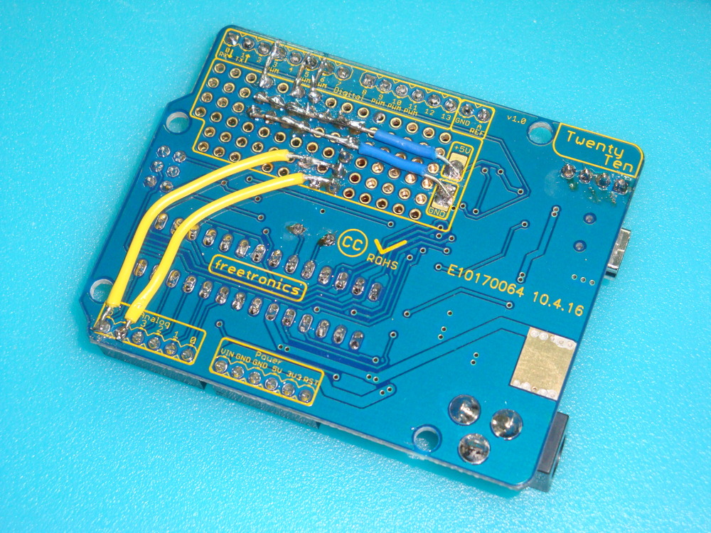

Now, on the test bed, I have the RTC clock working well using my beloved freeRTOS, and can get on with using the servos to drive analogue hands.


In the years since this instruction was writen, I’ve migrated to Github. So the code is hosted here. The freeRTOS code is also posted on Github. I used the Pololu Library for writing to the display, so it needs to be installed along with the normal AVR libraries.
Part 2 looks at building the PWM control for the retrograde hands, and adding a temperature function.
