Update May 12, 2013
I was testing my Arduino powered voltage controlled oscillator, when I noticed that the Right channel was very soft. Almost, but not quite, inaudible. Immediately, I suspected that there was a problem with one of the valves but, no, it was something else. Read more at bottom of this post.
Choosing the Elekit TU-879S
Looking for a new project, I decided to build a valve (tube) amplifier kit. So, let’s follow the process and see where it takes us.
I was looking for something that around $100, as a toy to play with. But it seems that that price level is unachievable, so we have to pay more. But, as the purchase price goes up, this thing can no longer be just a toy. It must become a functional durable product, that can actually be used by anyone.
There are a couple of valve stereo amplifier kits on the market, such as this Stereo Tube Amplifier Kit for under US$200, or this Model 16LS Stereo Integrated Tube Amplifier for US$250. Both looked good, and are cost effective. But, both suffered from the problem that they are built on a breadboard, and leave 300V exposed on open wires. Ok for a toy, but unusable in the long run for family members, or even my own careless fingers.
Some further research on the Internetz turned up the Elekit TU-879S, which seems to fit the requirements exactly. Less than AU$1,000 so it can be imported to Australia with no GST issues. Kit looks very well made, and professionally presentable. No loose HV wires to electrocute anyone. And, most importantly a very strong user community who have built and use the Elekit TU-879S in their audio systems, and provide input on modifications and improvements.
Oh. Oh. Think I just hit the “BUY” button.
Victor Kung at VKMusic created the English instruction manual used by Tube Depot. I just learned that unfortunately, Victor is getting nothing for his translation and original market development work. I suggest that you buy the kit from him directly.
This kit uses three valves, one a single valve dual Triode voltage gain stage, and two power gain Pentodes driving the output transformers, to produce 8W per Channel. All of the valves are readily available using either New Old Stock (NOS), or new products equivalent manufactured in Russia, or China. My finished version is pictured below, wearing ’58 Telefunken 12AX7, modern production SED Winged “C” 6L6GC, and alternatively ’61 production GE 6L6GC.


Research while waiting (on back order)
There are a couple of excellent reviews of the Elekit TU-879S which I won’t reproduce here. Save to say that they provided some ideas for improving, or hacking, the Elekit TU-879S, and that even before I had built it.
The first noteworthy improvement is to substitute the decoupling capacitors between the input and the pre-amp stage, and then before the power-amp stage. The Positive Feedback review suggests using VCap capacitors in those locations, and raves about the results. Great, but I’m not about to spend 50% of the total purchase price on 4 components. Let’s look for some cost effective alternatives.
The Internetz seem to suggest that Mundorf has a good name and quality product, so an order was placed for 4x MCap Supreme capacitors at Madisound Speaker Components. These MCap capacitors have a musical heritage, with dual series counter-wound cores supposedly cancelling impedance effects, but don’t add too much to the project cost.
The second improvement is to replace the existing dual linear variable potentiometer with a higher grade unit. The provided unit is a $2 ALPS plastic film component. For a little more, with respect to the value of the end product, the TKD 2CP-601S 100K stepped dual log taper potentiometer provides a good alternative. One was ordered from HiFi Collective in the UK. At about $40 it bridges a logarithmic gap in price between the original $2 component, and the ultimate component being a $300 stepped resistor array.
So with these two modifications, we have effectively upgraded the “small signal” part of the amplifier, where noise and non-linearity have the most effect. There are a number of other modifications suggested, but they are more drastic than simple component selection and replacement, and can wait until after I’ve established what the base-line of performance is for the Elekit TU-879S.
Valve search
The 6moons review goes into some of the options available for the Elekit TU-879S. Really, there are so many options around that it is a lifetime of experimentation to find the best valve sound from this amplifier. In fact, half the fun of this kit is reading the Internetz opinions on which valve creates what sort of sound. Often, strong opinions on individual valves are expressed without reference to the rest of the signal chain (pre-amp, speakers, listening environment, etc) such that the argumentation takes on a religious air.
12AX7 (Voltage Gain)
There are many many reviews of this 12AX7 valve type. Within these reviews there is one type that stands alone at the pinnacle of sound reproduction, the 12AX7 / ECC83 Telefunken with smooth plates. Luckily TC Tubes has some (one only as I write this) in stock. These valves have a 40,000 hour life time, so there is no problem to buy a “premium new” test device, with exactly matched triodes. The one that I received from TC Tubes was made in April 1958, and tests Gm 100%/100%, which is about perfect.
Also as an alternative, there are great reviews of the military version of the 12AX7 being the 5751 which has a lower gain (Mu of 70 vs. Mu100 for 12AX7), and is also extremely low noise. TC Tubes has these GE 5751 in stock too. TC Tubes shipped me a 1961 vintage GE 5751 with matched Gm 108%/108%.
There are many other alternatives of these valves, and as I mentioned, I think that they are all subject to a lore of selection.
6L6GC (Power Gain)
As the Elekit TU-879S accepts a variety of similar Pentode valves, it is difficult to determine which ones should be on the list to try. Cruising the forums, it seems that this amplifier works best with the 6L6GC, which is the same type that it ships with.
As the power valve has a limited (though long) life of around about 10,000 hours, I am not keen to spend a large amount of money on NOS for this position. So my ideal is to find the “best” modern valve and see what the service lifetime is in practice, before investing in a NOS alternative.
After looking at some reports at Watford Valves, I decided to get a matched set of SED Winged “C” 6L6GC valves, also from TC Tubes. These will complement the Electro Harmonix valves provided with the kit.
Once I’m sure that it is a good investment, in terms of sound quality and listening hours, I’ll certainly get some NOS power valves to use.
Update: I’ve decided to take the plunge on NOS Pentodes, and get some GE 6L6GC from TC Tubes. Reviews of these suggest that it has an excellent performance, exceeding any current production valve though possibly not the best available NOS.
The construction process
When you un-box the kit, with the components packed so neatly into 10 heat-sealed individual bags, and each piece of metal wrapped and separated by brown paper, you remember what the Japanese are famous for. OCD grade accuracy. Clearly, this kit is perfect.
The English translation of the instructions, and the inclusion of a 230V power transformer of the same type as the 100V original, are finesse added by Victor Kung at VKMusic. There is no need to add any further internal photographs of the process. Assembly, for someone who is used to soldering SMD and micro-electronic components, is a breeze. Absolutely everything is explained exactly, and everything is perfectly easily done.
The English translation has two small (tiny) typos in resistor numbering, which confused me for a minute (also OCD), but looking at the Japanese original instruction cleared up my confusion.
As the provided resistors are 5% accuracy specification, during the construction process I checked the actual resistance of all resistors before assembly using an accurate digital multimeter, and tried to match closest pairs of resistors to the same circuit position in both Left and Right channels. The thought behind that was that even if the circuit was very slightly off specification because of the tolerance in the resistor values, then at least Left and Right channels would be matched.
The modification process
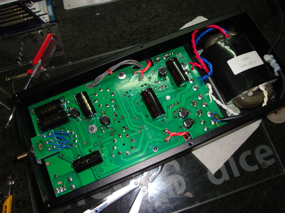
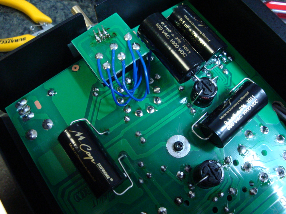
With the Mundorf MCap Supreme capacitors being much larger than the standard polypropylene capacitors they have to be fitted onto the back of the PCB. No problem, there is plenty of space.


The TKD 2CP-601S potentiometer is a little more tricky. Fortunately, the pin-outs are identical to the supplied device, so the volume control PCB can be used. I just needed to kink the pins towards each other slightly to get a fit. The volume circuit PCB shows some minor flux damage, as I had to remove the provided volume potentiometer fitted first for testing.
The axle housing on the TKD 2CP-601S is slightly greater diameter than that provided, but rather than drilling out the top cover I decided to use a pocket knife to cut “flats” on the two sides of the threads since it almost fit. As the housing metal is aluminium, and it is cut into a fine thread, it is easy to remove enough metal from both sides with a knife to get the potentiometer to fit cleanly into the slot. This could alternatively be done (better) with a small flat file.
Secondly, the tab on the front face needs to be removed so that it will fit flush with the front panel. Snip with side cutters, and it is gone.
Finally, the axle is about 5mm longer than that on the provided pot. I used large pliers holding the end of the axle to hold it still, whilst using a small hacksaw, resting against the pliers as a guide, to cut through the soft brass. Easily done. Don’t hold the body of the potentiometer when cutting, otherwise the axle will turn, and you will surely damage it. Use a file to tidy up the cut edges on the axle.
Testing & listening
The initial testing and listening was done using the provided Chinese 12AX7 and Electro Harmonix 6L6GC valves. Everything worked well. The amplifier is amazingly quiet on idle. No audible hum at all. If a line level source is connected into one input, with the other input selected, some crosstalk can be heard at high volume. But generally this is not noticeable, and can be removed simply by switching off the alternative source.
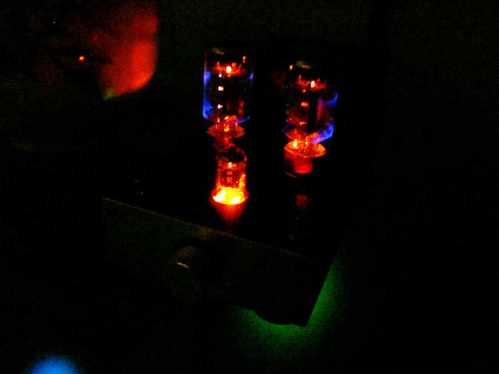
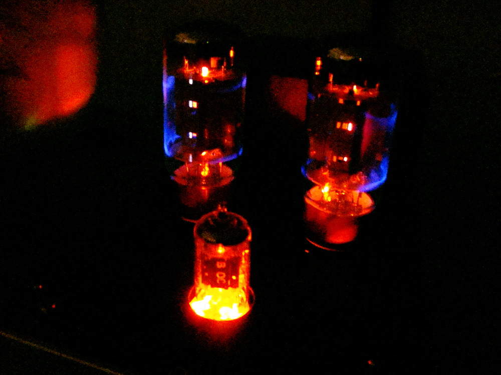
Both the SED and Electro Harmonix valves produce the lovely blue aurora surrounding the valve, when viewed in the darkness. The pictures below try to capture it, but don’t do it justice. The GE valves don’t produce the blue aurora, but that doesn’t affect their excellent sound quality.
Once the proof testing was finished, I replaced the standard valves with the special NOS 1958 Telefunken 12AX7, and the matching 1961 GE 6L6GC valves. Amazing the difference in sound quality. After a few hours of burn-in, I started listening to the U2 War album, and I could swear that Bono started to sound incredibly like Elvis. Some of his spirit must be trapped inside the little glowing bottles.
Repair Update
Early May 2013, I was experimenting with a voltage controlled oscillator to see how sine waves would behave, and to test my speakers and my ears, when I noticed that the Right channel had become almost inaudible. I hadn’t previously noticed, or may be I had noticed but had put it down to my speakers being too old.
I did some standard trouble testing, and found all the valves to be good and also inputs and speakers to be good. It therefore had to be something inside the amplifier.
I gathered all my tools, slightly concerned that it would be hard to identify what was the problem. I needn’t have worried. The problem was obvious. Burnt black obvious.
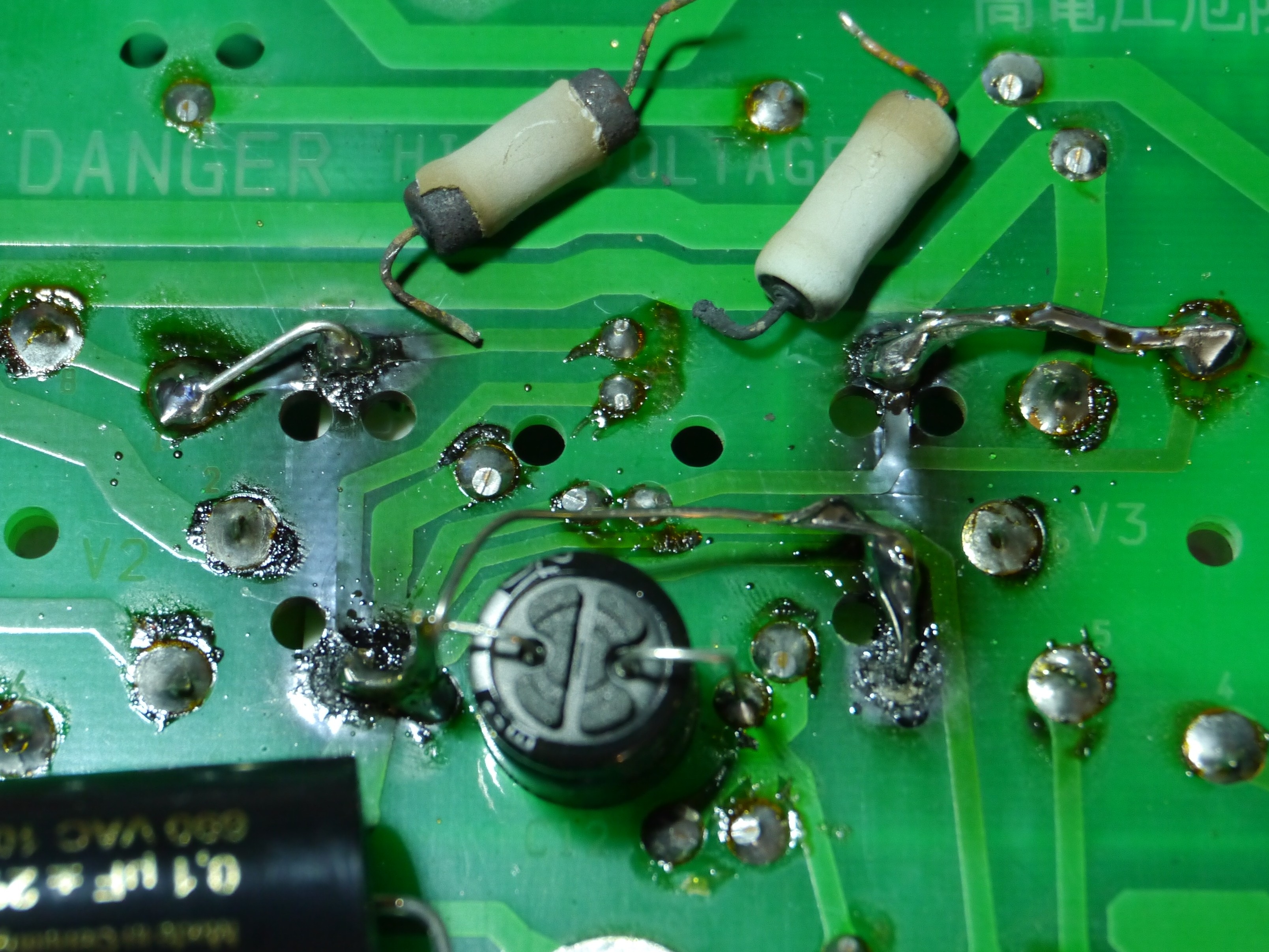
Electrically, R13 and R14 are 330 ohm 3W resistors, which provide the current load for the power valves. At idle they should present about 21V on Pin 8 of each of the power valves. In my measurements, the left channel was presenting at 28V and the Right channel at 58V. The significantly lowered current through the Right channel was causing the reduced amplification.
As soon as I turned the board over, the Right resistor sort of just fell off the board. Pretty well burnt out.
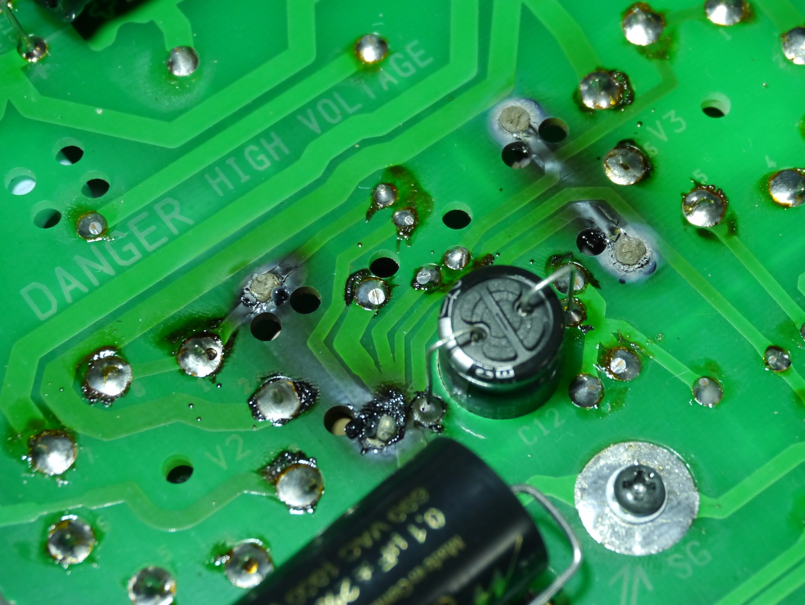
I have replaced the faulty pair R13 and R14 with 330 ohm 5W resistors, and have done a little bit of aerial bridging to try to support the weakened PCB tracks. The image below shows the result. It is not pretty, but it has returned the amplifier to working, with 22V showing on each of the valve’s Pin 8, and the volume level from each channel being similar.
My suggestion, use 5W resistors when you’re making this kit, and try to keep enough space around the resistors so that they don’t burn the nearby capacitors and sheathed wiring. In the photo the faulty resistors can be seen too, with the lower leg on the Right resistor almost turned to carbon powder.