Dogbot – Post 6 – Back on (PID) track

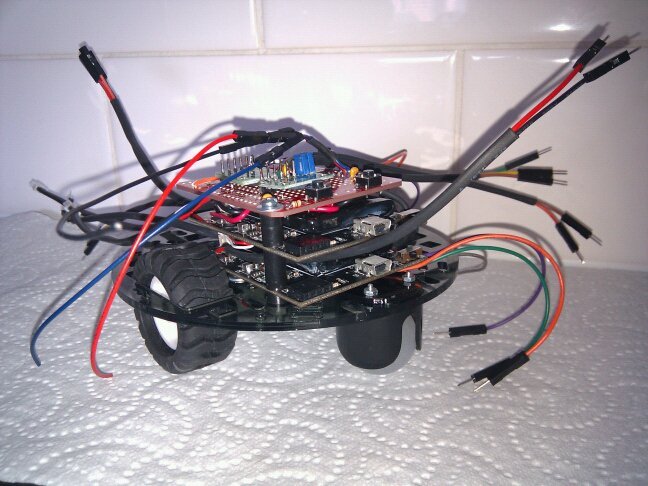
Exactly a year has passed since my last post on the Dogbot. I ended up getting very frustrated with my inability to get sensible odometry out of the Pololu Encoders using the Orangutan SVP auxiliary processor, and needed to put the project aside for a while.

I believe that I spend a good few weeks digging into the code, to see why I wasn’t getting sensible readings from either, or at times both, of the sensors. Then I gave up, and took up an easier challenge being learning PWM control, and started building the Retrograde Clock.

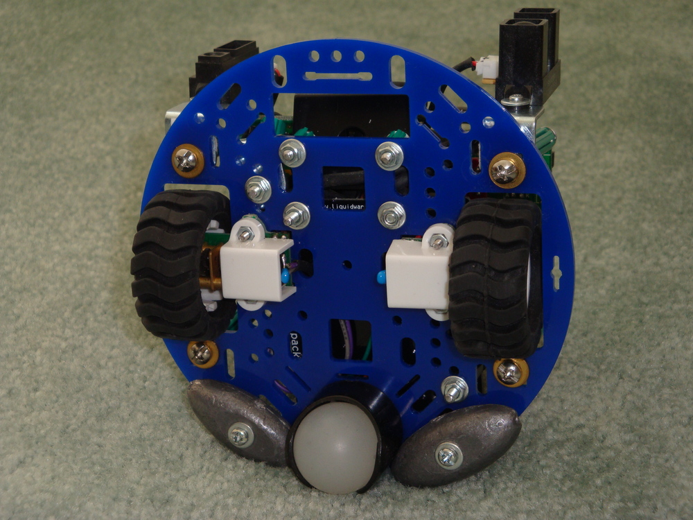
Recently, I picked up the Dogbot again, and determined that I would make it work. I worked out that one of the Encoders was not right, using my excellent new Seeedstudio DSO Nano. So, then I ordered a new Encoder. At the same time I ordered a new chassis for Dogbot, as the old one was damaged by my cleaner, and decided to replace the medium capacity Liquidware Backpack, used for driving the motors, with a high capacity variety.

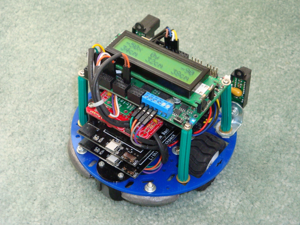
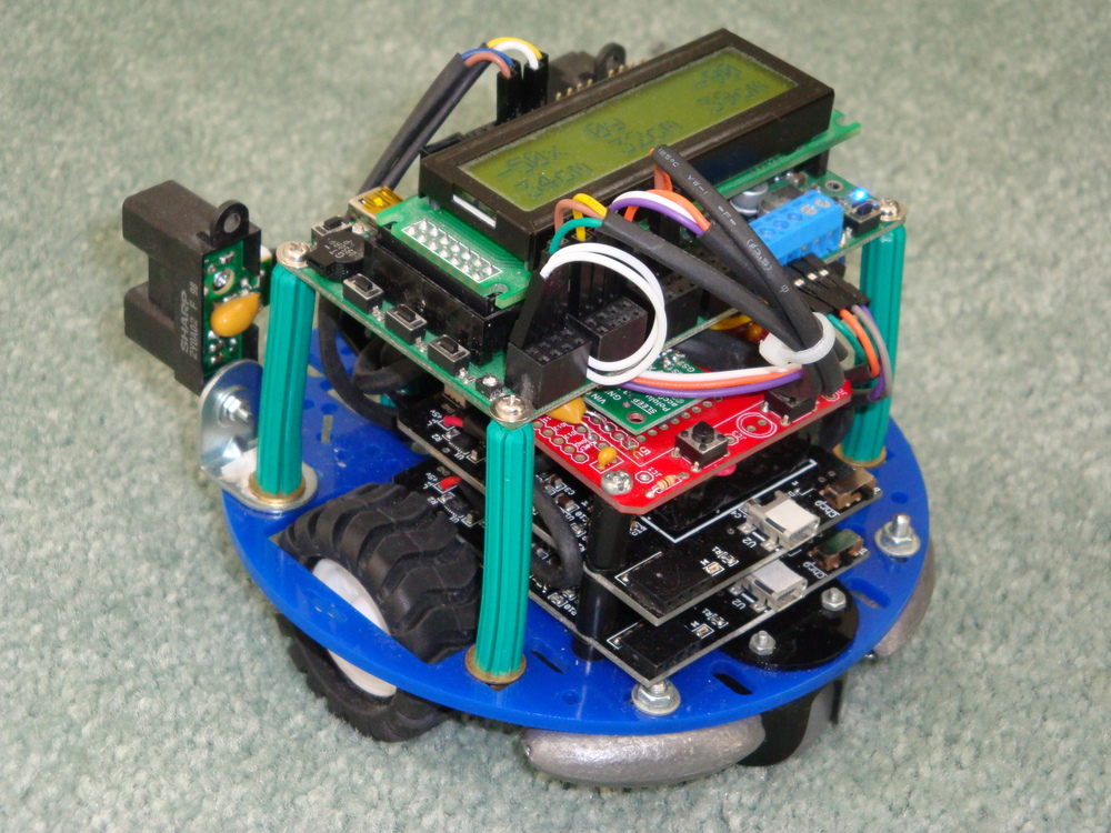
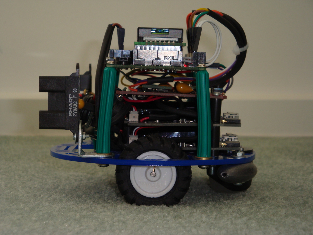
I took the opportunity to rebuild the dogbot onto the new chassis, and to simplify the system to make it more robust. One construction change was to use the Wall Plugs as a flexible structure, and screw into their ends, rather than using them as a spacer with a bolt through the middle. This allowed me to use the ends of the wall plugs as mounting points, because they could be fastened tight. Previously, because of the angles, they had needed to remain relatively loose.

Dsc04118Dsc04119

I have removed the rear mounted PIR sensor at this stage. It is easy to add again, at the appropriate time.

Dsc04116Dsc04117

Following reconstruction, I found that the Encoders continued to give unusual (wrong) results. Finally, I looked into the details of the encoder outputs again, using the DSO, and realised that their outputs really NEED to be exactly tuned, using the tiny pots, to 50% duty square waves, otherwise the Orangutan SVP cannot get an accurate count. With this fixed, then the Odometry was built up accurately, measuring the count to travel a fixed distance. With this figure, the actual diameter of each wheel can be calculated, and hence the travel required to go in a straight line.

It is important to note, that Dogbot doesn’t go in anything like a straight line, with full power applied to each motor. The friction, and wheel size differ enough to make it curve quickly from the straight and narrow. So PID is absolutely necessary to keep it running straight. With PID implemented properly then, finally, Dogbot runs straight.

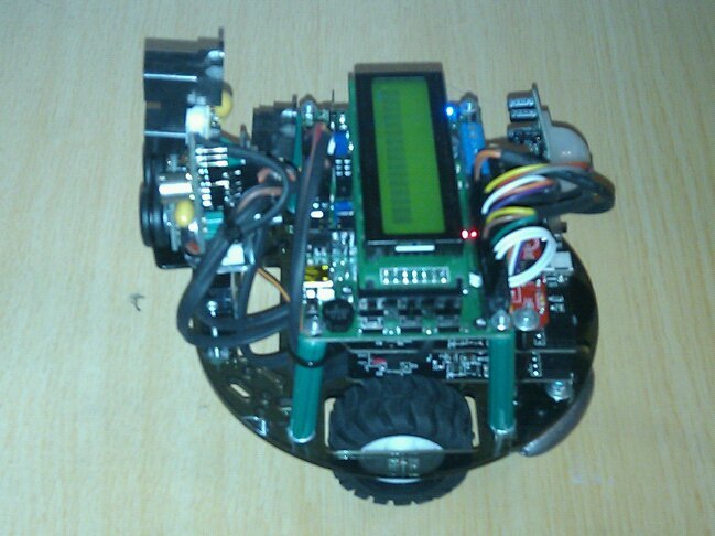
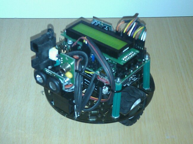
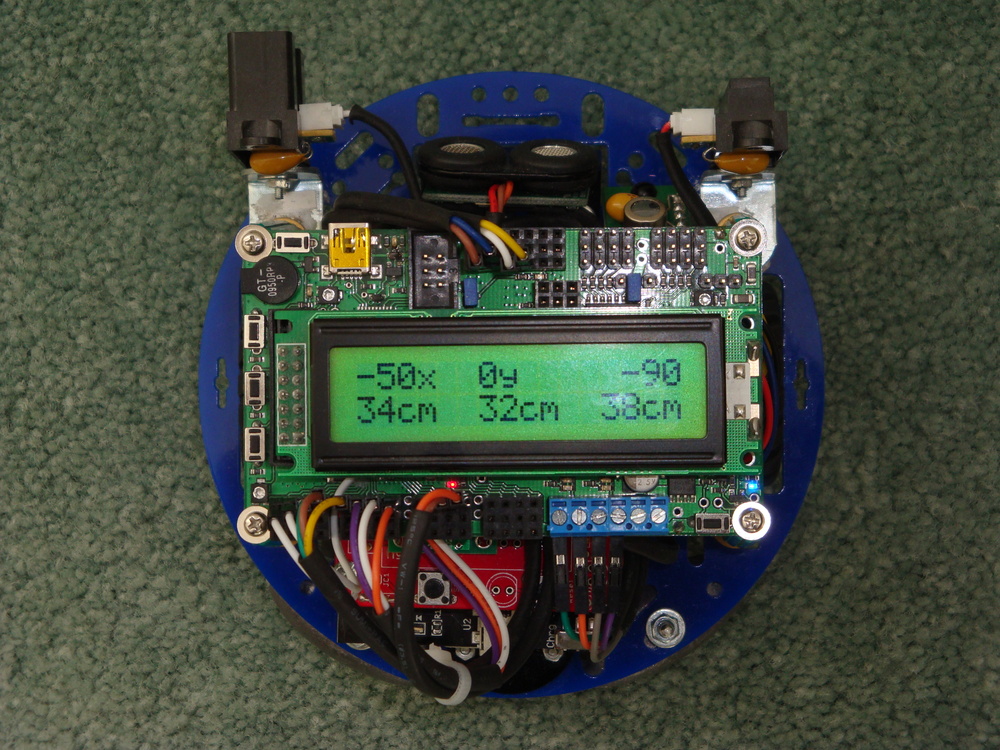
These photographs are taken with the display indicating two items. On the top line, the target distance, represented in x and y distance to travel, is noted. Also the deviation from correct heading to target. The instruction is requesting Dogbot to travel 50cm along what it has been told is the x dimension. The instruction is also implying that the Dogbot is initially facing in y direction, and needs to rotate its poise 90deg clockwise to face along x, before it begins its travels.

Dsc04125

The code is set up to all allow specification of an initial poise, and a final poise, as well as x and y distances to travel, for the Transport Task to undertake.

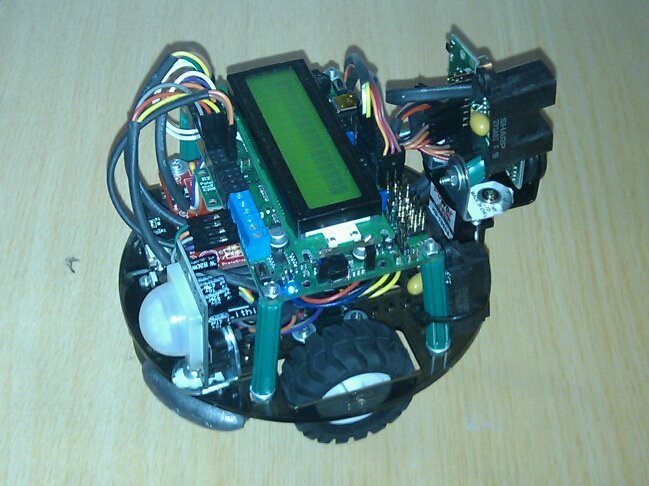
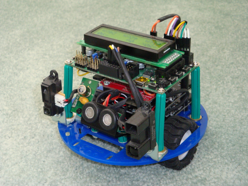
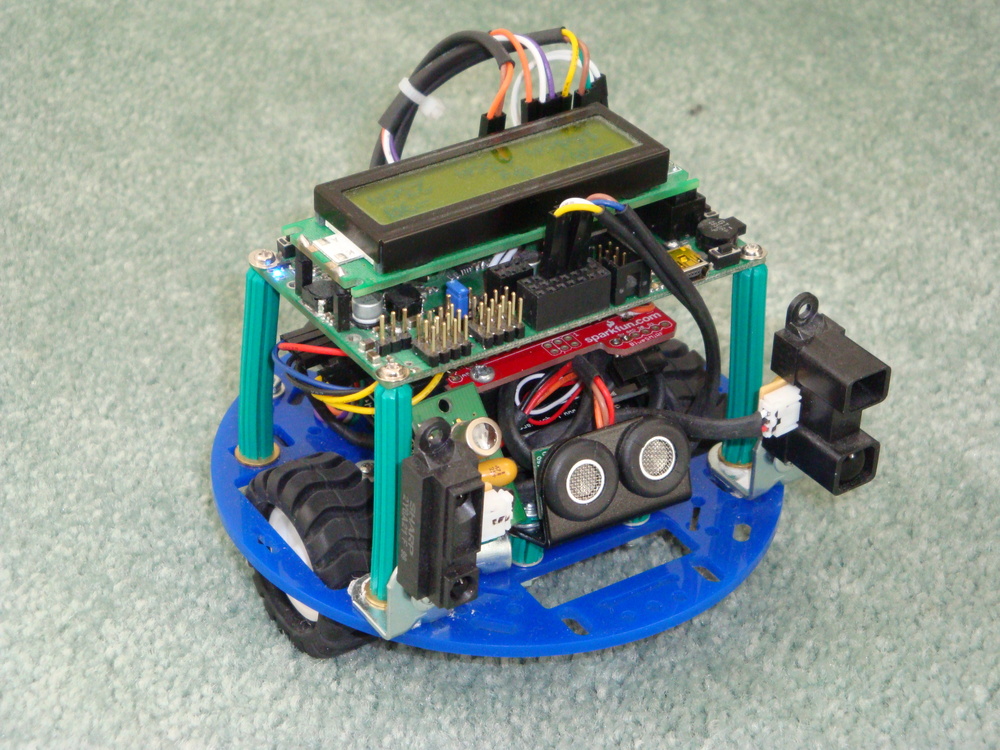
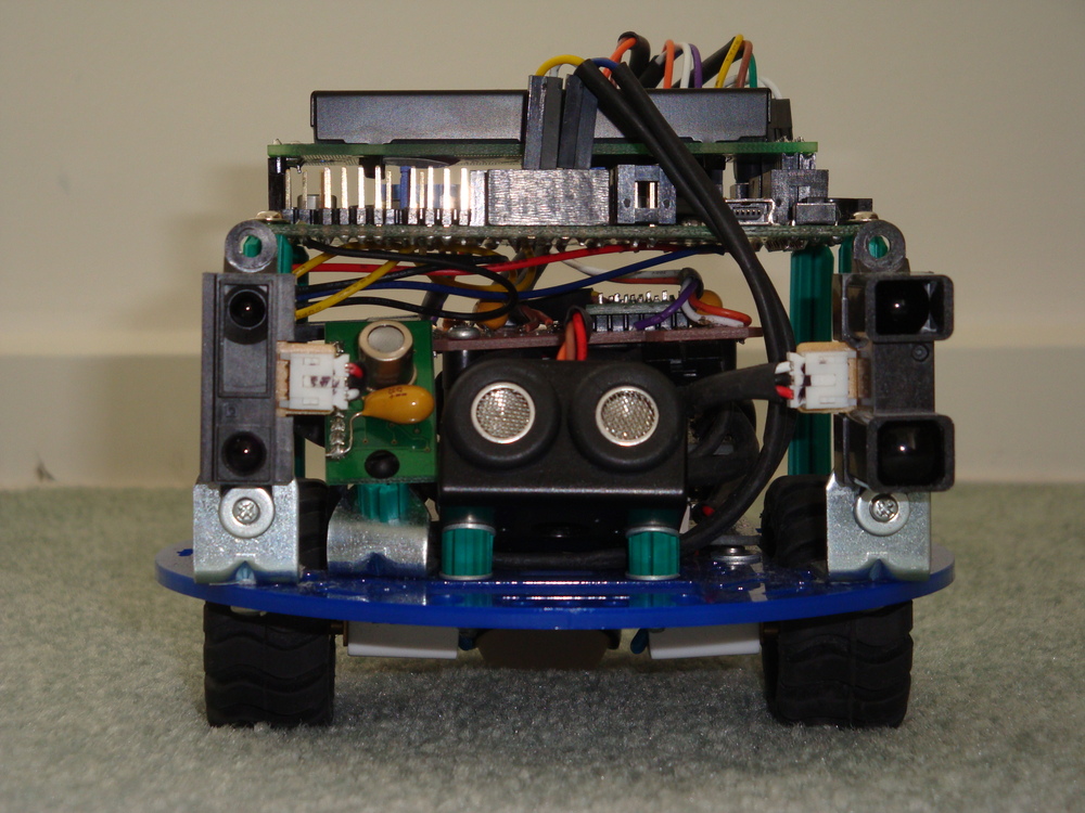
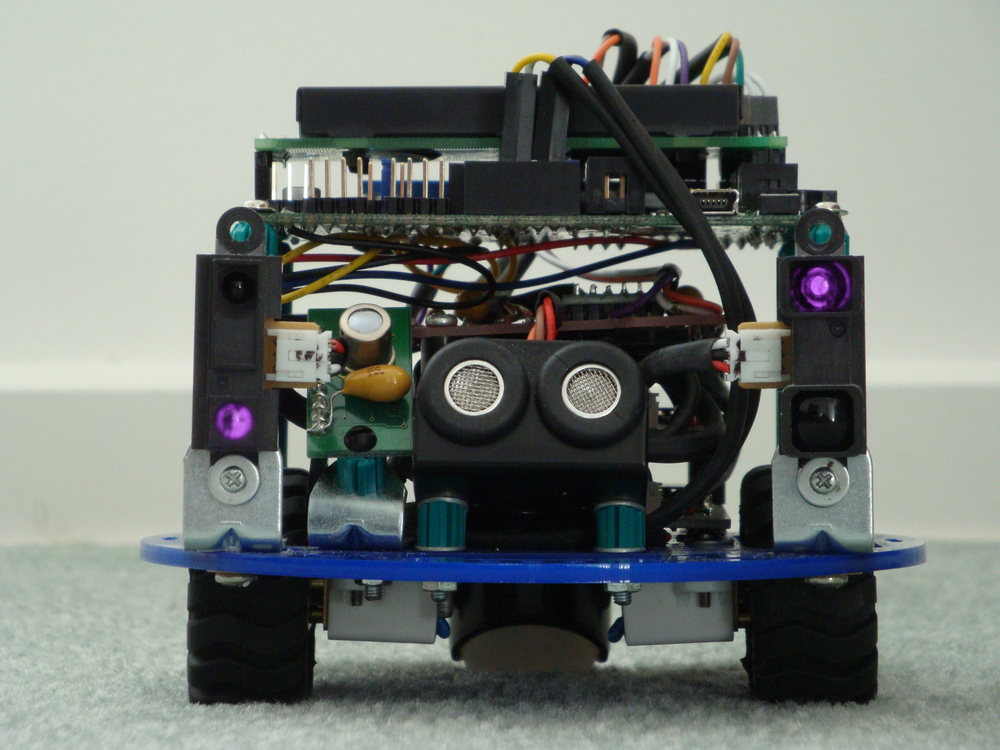
The bottom row of the display shows the distance reading indicated by each of the three sensors across the front of Dogbot. Central indication being the I2C ultrasonic sensor, which is very accurate, but not at all directional. Left being the long range IR sensor, and Right being the medium range IR sensor. These sensors are very directional and can differentiate a thin rod or edge of a hand placed in front of them. Combination of these sensors will enable Dogbot to travel safely in a forward direction.

Not displayed is the output from the I2C thermal sensor. It has been tilted back, so that its vertical array of 8 pixels is looking up from +5deg to +70deg. It can see very small differences in temperature from ambient, which it also reports.

At this stage my work continues to get the Dogbot to consistently travel from one location/poise to another location/poise. Whilst I have the code in a state that it can achieve this, it doesn’t yet do it consistently, because of variables in the drive system that need to be properly tuned. And, I could improve the code a lot too. The code is a bit amateurish.

Notes to photographs

Dsc04122Dsc04121Dsc04124Dsc04123Dsc04127

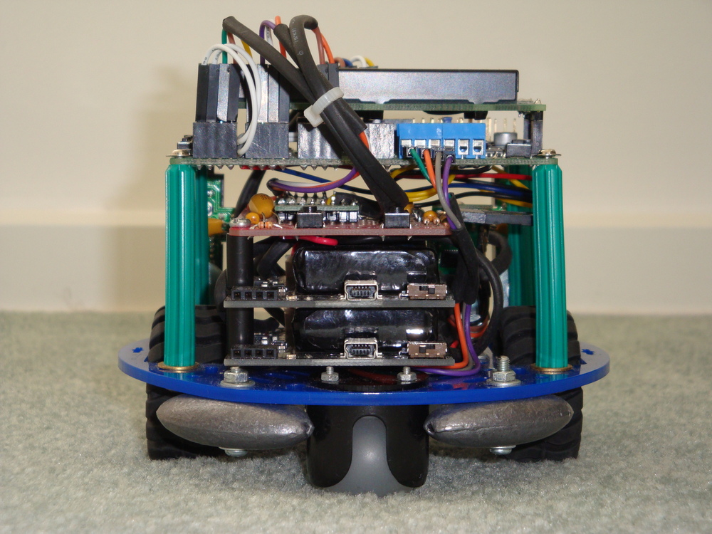
Liquidware battery packs have a on/charge switch that effectively isolates the battery. This has proven useful, as I can turn the motors off, whilst still programming the Orangutan SVP. Not designed, but in hindsight very useful.

To counter sagging voltages, and noise on the supply lines, I have fitted 1uF Tantalum capacitors on all of the sensors. This helps to ensure that they are getting a good supply when they are firing.

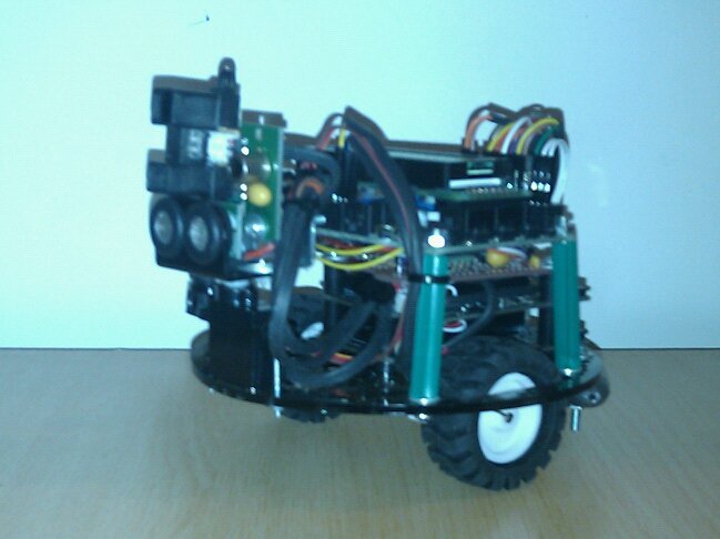
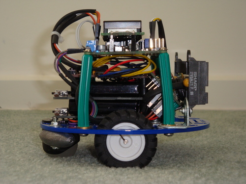
Both Thermal array sensor, and Ultrasonic distance sensor are canted up to get their cone of vision away from the floor. I have left the IR distance sensors facing parallel with the floor, as they don’t get false readings from the floor (assuming it is flat), and I don’t want to miss low objects that might interfere with the Dogbot.

I added the fishing weights to the rear of Dogbot to ensure it had good balance. It has sufficient weight to rear from the batteries to stand up properly, but when braking it is quite top-heavy. So, the low heavy weight at the rear helps to ensure that it doesn’t tip over.

Although there are no other items on the motor circuit, I have added some 1nF bypass capacitors on the motors. Can’t hurt.

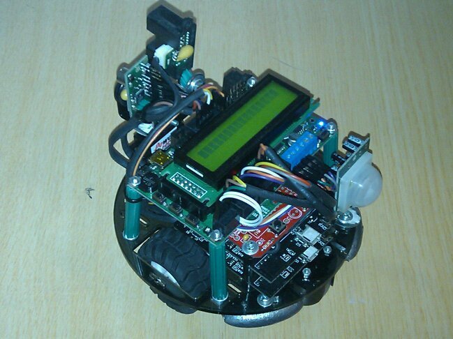
It is alive. Here the IR glow from the sensors has been captured by the camera. Perhaps Skynet lives?

Dsc04130

My next steps are to finish the Transport Task so that it can reliably go from point to point. Then, I’ll integrate more information into the Transport task from the accelerometer sensors, to improve directional accuracy. Then to build some mapping code to allow obstacles to be located and avoided.

DogBot – Post 5

So some time has passed and I’ve had some success with different aspects of my robot.

For simplicity, I’m using a test bed based on an Arduino Duemilianova connected to a Nerdkits sourced display. I’ve hooked the display up as if it was a Pololu Orangutan SV-328 and am using Pololu libraries to write to it. Also, I’ve been working on the actual SVP based robot, so both of which are working well.

The processor 328p is used for the Duemilianova and requires the use of the Timer0, which implies no Pololu motor library code is possible without conflicts. However this is not an issue, as the Duemilianova doesn’t have motor drives anyway. The actual DogBot has the 1284p which is used in the SVP and uses Timer3, which has no limitations on any known libraries to my knowledge.

The freeRTOS code is posted on the Pololu Forum, mostly just back-up as the application code is very immature.

At  this stage I’ve got all of the I2C bus based sensors working, based on code developed by Fleury. So, I can read the thermal sensor for its 8 pixels, and equally importantly, I can read the SRT10 Ultrasonic Sensor for distance in cm. One issue with the ultrasonic sensor is that its field of vision is so great that it basically detects anything “in front” of it. Good to not run into things, but pretty useless as a fine directional capability. It seems lucky that the Sharp IR distance sensors are very directional, and sufficiently accurate as a complement. The analog sensor readings are working well too, though I still have to create a ADC to cm regression.

From the point of view of sensing, it looks like the Sharp IR sensors will be the reference. With the SRT10 sonar being most relevant to create a “zone of safety” where I can be assured that the nearest object in a cone of 120deg is measured, but can’t be sure exactly which direction the object is. On the thermal side, I will get a vector (direction and temperature) from the sensing location, but no distance. But, that I knew and expected.

Putting some effort into designing the motor control, or Transport Task, has taken up my thoughts recently. I don’t want to link the odometry available from the quadrature encoders back into the mapping or routing task. Similarly, I don’t want to link the intertial navigation available from yaw and linear acceleration sensors into the motor task.

I think the transport task should simply take a vector,  relative to the the current pose of the robot, and execute these translation commands subject to feedback from odometry, leaving the inertial navigation to another task.

This fits well into the design of the hardware, as odometry can can be queried from the Pololu SVP ancillary processor, without blocking, and the motor PWM drivers can be also managed without blocking other tasks. This creates a self contained task that does not need to share resources with other tasks.

However, the inertial sensors are analogue readings and the ADC will need to be shared with the Sharp IR distances sensors. Creating the need for a semaphore, and blocking based on the availability of the ADC.

Because of the battery issues described in Post 4, I’ve had to remove the servo neck of the DogBot. Therefore, I will implement the option for motion to be along circular paths, as well as along a straight line. Motion along a straight line, with stationary rotations to create the correct pose prior to departure, are the best paths to arrive at the destination with the lowest risk and shortest path. However, with a fixed sensor head, straight lines don’t fill the map with information as they leave the sensors always pointing in the same direction.

If the DogBot proceeds from A to B via a circular route (if this is requested by the mapping or logistics task), then the sensors will be pointed at all directions from +90 to -90 degrees along the path to the destination. Allowing the travel time to be used effectively for data acquisition.

If I’m feeling smart, then I can create any number of route subdivisions, and force DogBot to describe a path of smooth semicircles to the destination, gathering sensor data along the route.

The inertial sensors can be run in a parallel task (using the ADC along with the Sharp IR sensors), with the odometry (from the ancillary processor) to cross check that the expected distances and directions are traveled. Whilst I think the odometry is more likely to be accurate, the map will be updated constantly so some inaccuracy should be expected and tolerated by the code.

My next step is to design this transport task. This task should take distance, bearing and path description (straight line, circle, sinusoidal, etc) and carry it out to the best of its ability (odometry PID data only). I expect resolving this effort will take the next few weeks, and perhaps longer.

Later work is to develop the logistics and routing task that will issue the navigation requests to the transport task.

Continued with Post 6 (one year later).

Dogbot – Post 4 – Hardware & freeRTOS Complete

Ok so some time later, I’ve finished building up the hardware.

It is basically a 4 level stack, with the two Li batteries on the bottom, followed by a proto board which carries the acceleration sensors, and distributes power and signal lines.

The top level is the Pololu SVP and its daughter display card (level 5).

25742_419162736067_610931067_5621385_2222535_n
25742_419162646067_610931067_5621384_4844593_n
25742_419162756067_610931067_5621386_5021337_n
25742_419162776067_610931067_5621388_4697390_n
25742_419162806067_610931067_5621389_6666628_n
25742_419162876067_610931067_5621390_4382446_n

What issues are there?

Well electrically none. All the signals are working perfectly, as demonstrated by the Pololu Analogue and Digital code, together with their motor and servo code. All the hardware seems to be functioning perfectly.

But, there are some problems.

The Li battery packs are incapable of providing enough current. I should have done a power budget before building. Everything works pretty well, although there is some voltage droop to 4.5V, until I turn on the neck servo. Then Vcc drops to 3.5V and the DogBot dies.

So the choices are to remove the servo, and program the scanning function using the body, or build a new boost power supply. At this stage I’m tending to think it would be better to just remove the neck servo, and use the chassis for scanning.

Also finished is the freeRTOS port, using Timer3 from the Atmel MegaAT1284, which is not found on other devices of this type. This allows me to have no conflicts with previously written code (using Timer0, Timer1, or Timer2). However, I will still need to go through all libraries to ensure that they don’t cause problems by being interrupted by the RTOS.

So now onto some heavy system design to work out exactly how to implement the mapping and searching functions, and how to drive in a straight line.

Wifi Dogbot – Post 2

Construction NOTES

   1. Build chassis platform for use indoors.

Chassis platfrom elements come from Pololu, so it will be good to use their Orangutan libararies wherever possible. I will need to modify them as the Arduino/Blackwidow runs at 16MHz (not at 20MHz).

Should I modify Arduino/Blackwidow to use 20MHz crystal, to save modifying all the Orangutan, and also to gain 33% more cycles/sec? Or, modify all the code and timing?

Webbot Lib is a library that addresses most issues associated with building robots. Version 1.15b is current now.
http://webbot.org.uk/iPoint/30.page

   2. Build motor controls to allow straight line, radius, and Bézier motion.

Basic information on how to get differential drive working.
http://www.societyofrobots.com/programming_differentialdrive.shtml

Then how to add PID control to the system.
http://www.societyofrobots.com/programming_PID.shtml

Some of the Orangutan & Pololu libraries are directly relevant:
OrangutanMotors – basis for control of the DC motors.
PololuQTRSensors – basis for reading the Quadrature sensors from Pololu.
PololuWheelEncoders – basis for reading the Encoders on the Wheels.

CourbeBezier Libraries are interesting for describing Bezier curves.
http://jppanaget.com/doku.php/wiki:bezier_curves

   3. Build emergency collision avoidance.

Some of the Orangutan & Pololu libraries are directly relevant:
OrangutanPulseln – basis for reading the short range sensors.
OrangutanDigital – basis for reading the short range sensors.

   4. Build long distance sensors.

A very good description of the chosen Sharp optical rangefinders.
http://www.societyofrobots.com/sensors_sharpirrange.shtml

And this is a description of the Sonar Ultrasonic rangefinders.
http://www.societyofrobots.com/sensors_sonar.shtml

Some of the Orangutan libraries are directly relevant:
OrangutanAnalog – basis for reading the Sharp Optical Rangers

   5. Build voice box – bark, growl, yap, whine, etc.

This code at Arduino might be useful.
http://www.arduino.cc/en/Tutorial/PlayMelody
http://www.arduino.cc/playground/Code/MusicalAlgoFun

   6. Build area mapping.

Using the wavefront technique seems very relevant, from Society of Robots
http://www.societyofrobots.com/programming_wavefront.shtml

   7. Build aggressive object collision avoidance.

Some of the Orangutan libraries are directly relevant:
OrangutanSPIMaster – can drive the interfaces with the WIFI device on Blackwidow.
OrangutanSPIMaster – can drive the interfaces on the Ultrasonic Ranger.

Use the 6DOF Atomic Gyros & Acelerometer code as basis

   8. Build aggression response.

Some of the Orangutan libraries are directly relevant:
OrangutanSPIMaster – can drive the interfaces on the Acceleration & Yaw sensors.
OrangutanSPIMaster – can drive the interfaces on the Ultrasonic Ranger.

   9. Build WiFi sensors & target mapping.

Some of the Orangutan libraries are directly relevant:
OrangutanSPIMaster – can drive the interfaces with the WIFI device on Blackwidow.

A general website for location technique comparisons
http://www.positioningtechniques.eu/lbs_technique_checker.asp

The RTLS from 802.11k is useful, as are the equations for solving based on iso-power intersections of two circles.
http://mathworld.wolfram.com/Circle-CircleIntersection.html
http://local.wasp.uwa.edu.au/~pbourke/geometry/2circle/
There is a C code example to be followed.

  10. Build intelligence logic to enable end result.

Webbot Lib is a library that addresses most issues associated with building robots.
http://webbot.org.uk/iPoint/30.page

Use the Seeker2 source where possible, from Society of Robots.
Research into finite state machines required.

Also there is an Experimental Robot Platform code that is being provided ERP_WebbotLib
that will be very relevant.
http://www.societyofrobots.com/robot_ERP.shtml

  11. Build Thermal sensors & target tracking.

Some of the Orangutan & Pololu libraries are directly relevant:
OrangutanServos – can drive the PCM interfaces to the pan servo for Thermopile Sensor (option).

WiFi Dogbot

I was looking for a “why” for investing my time in Atmel AVR devices, because with a “why” progress is always faster. I think making an autonomous robot with dog-like behaviour will make an excellent one / two year multi-layer project, that will be able to demonstrate itself at the end. Also it won’t consume too much cash.

This post is to create a problem description, expected outcomes, and path I’ll be taking. It will also be a reference when I forget where I was going with this.

Why?

  • Being able to find my ‘Droid when it has gone missing around the house, and (more reguarly) being able to find my wife’s Crackberry is a fairly regular occurrence. So, I’d like to build something that can find both of these WiFi enabled devices. Also, being able to search out iPhones and WiFi APs, like a drug sniffer dog, would be mildly entertaining for family and visitors.

Expected features

  • Autonomously seek out and approach WiFi sources in order of strength.
  • “Bark” when the device is in close proximity.
  • Navigate & travel at dog speed in an unfamiliar environment.
  • Avoid aggressive obstacles within the map. “Growl” at these obstacles.
  • Reorientate autonomously if an aggressive obstacle “picks up” or “plays”.

Optional features

  • Follow someone around whether or not they have a WiFi device.

Assumptions

  • The floor is flat. Litter can be avoided. -> a cheaper indoor chassis can be used.
  • The room is small. 10m x 10m map can be built, with translation as map edge approached. -> memory conservation.

Initial Plan

  1. Build chassis platform for use indoors.
  2. Build motor controls to allow straight line, radius, and B?zier motion.
  3. Build emergency collision avoidance.
  4. Build long distance sensors.
  5. Build voice box – bark, growl, yap, whine, etc.
  6. Build area mapping.
  7. Build aggressive object collision avoidance.
  8. Build aggression response.
  9. Build WiFi sensors & target mapping.
  10. Build intelligence logic to enable end result.
  11. Build Thermal sensors & target tracking.

Component sourcing

  • Chassis

1x Pololu 5″ inch Robot Chassis RRC04A http://www.robotgear.com.au/Product.aspx/Details/353
1x Pololu 42 x 19mm Wheel and Encoder Set http://www.robotgear.com.au/Product.aspx/Details/307
1x TB6612FNG Dual Motor Driver Carrier http://www.robotgear.com.au/Product.aspx/Details/319
1x Pololu Ball Caster with 1″ Plastic Ball http://www.robotgear.com.au/Product.aspx/Details/370
2x 30:1 Micro Metal Gearmotor http://www.robotgear.com.au/Product.aspx/Details/344

1x Arduino Duemilanove http://arduino.cc/en/Main/ArduinoBoardDuemilanove
(will be replaced in step 9.)
1x Arduino Proto Shield http://www.sparkfun.com/commerce/product_info.php?products_id=7914

  • Emergency Sensors

3x Pololu Carrier with Sharp GP2Y0D810Z0F Digital Distance Sensor 10cm
http://www.robotgear.com.au/Product.aspx/Details/309

  • Long Distance Sensors.

2x Sharp GP2Y0A02YK0F Analog Distance Sensor 20-150cm http://www.robotgear.com.au/Product.aspx/Details/272
1x SRF10 Dual Transducer Ultrasonic Ranger http://www.robot-electronics.co.uk/htm/srf10tech.htm

  • Voice Box.

1x Piezo Buzzer from NerdKits

  • Aggression Sensors.

1x MMA7260QT 3-Axis Accelerometer http://www.pololu.com/catalog/product/766
1x LISY300AL Single-Axis Gyro http://www.pololu.com/catalog/product/765

  • WiFi Sensor (and revised Microcontroller Platform).

1x BlackWidow 1.0 http://www.seeedstudio.com/depot/blackwidow-10-p-613.html

  • Thermal Sensor.

1x Thermopile Array http://www.robotgear.com.au/Product.aspx/Details/294

So, maybe the next post once some more details are to hand.