AVR Pong – Peggy2 & Danger Shield

This post should really be titled “AVR Pong, and some other non-firsts”.

Avrpong

I saw the Peggy2LE and decided that it was something that I just had to have. I mean, 625 LEDs on one board can’t be bad, right? Well at least that was what I thought, until I tried to solder 1250 LED leads in one night.

Peggy2le

Anyway, to make a point out of this, I decided to make a Pong game, using the Peggy2 and a Danger Shield courtesy of Little Bird Electronics

So why is this interesting? Well there are somes significant firsts in there for me.

  1. Not just multi tasking (using freeRTOS), but real multi-processing using 2 AVR devices. The two AVRs communicate using the I2C bus.
  2. Developing an I2C code base that can simultaneously be Master and Slave, and is interrupt driven. I hope that the code can do MultiMaster too, but I haven’t fully tested it.
  3. Building a robust efficient video transfer protocol between the game mechanics AVR and the video (Peggy2) AVR. Using prioritised row updating and a CRC8, which I think it is pretty robust.
  4. Building a buzzer routine that can play melodies, with real notes, again fully interrupt driven, using Timer 2 (the Danger Shield buzzer is connected to PD3).

None of these things are original. In fact most of the code is borrowed from elsewhere, and the sources can be found in the files. But, I’m pretty stoked to have made it all work together, under freeRTOS. Small things, as they say, amuse small minds.

Code at AVRfreeRTOS at Sourceforge.

Updates with more detail when it is not so late.

freeRTOS and libraries for AVR ATmega with Eclipse IDE

I’ve created a Sourceforge project as a place to host all my current tools and working environment. The Sourceforge site is now 4 years old, and there’s a GitHub site too, which is now the most up to date repository

Preferred: Github freeRTOS & libraries for AVR ATMEGA

Secondary: Sourceforge freeRTOS & libraries for AVR ATMEGA

The Sourceforge repository has become so complex, with so many libraries, I thought that it was about time to make a simple version, which has the minimum implementation to get started. No additional libraries included. One timer option, using the watchdog timer. One heap option, using avr-libc malloc. One example application, just a blink with two tasks, for Uno, Mega, and Goldilocks boards.

Github minimum AVRfreeRTOS

The thing about open source. Sometime you have to give back.

Things I’m really happy about:

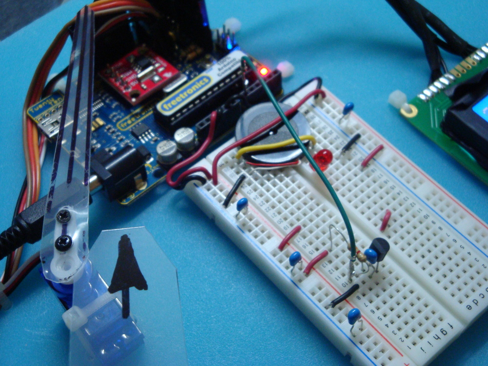
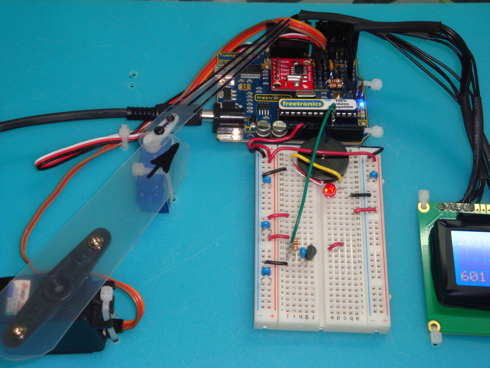
  • Arduino Uno family ATmega328p, Freetronics EtherMega (Arduino Mega2560), and Goldilocks ATmega1284p, scheduling and IO works.
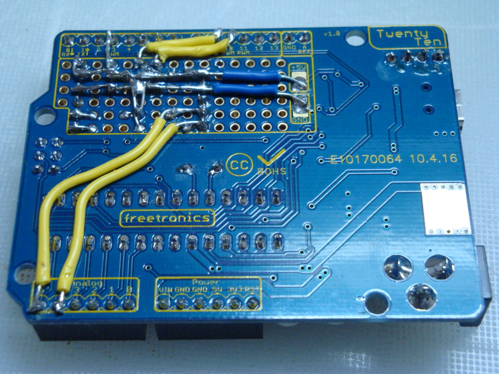
  • Being able to use any Timer on the AVR as the system Tick. In practice this means Timer0 on 328p (Arduino Uno), Timer3 on 2560 (Arduino Mega) and 1284p (Pololu SVP) and Timer2 on 1284p with 32.768kHz watch crystal (Freetronics Goldilocks). The watchdog timer has also been implemented, and if there is no critical need for accurate timing, this is the lowest resource impact system tick.
  • Converting all of the relevant libraries to be friendly to a RTOS system. No delay busy-wait loops etc. Everything defers to (is interruptible by) the scheduler when waiting, or is driven from interrupts.
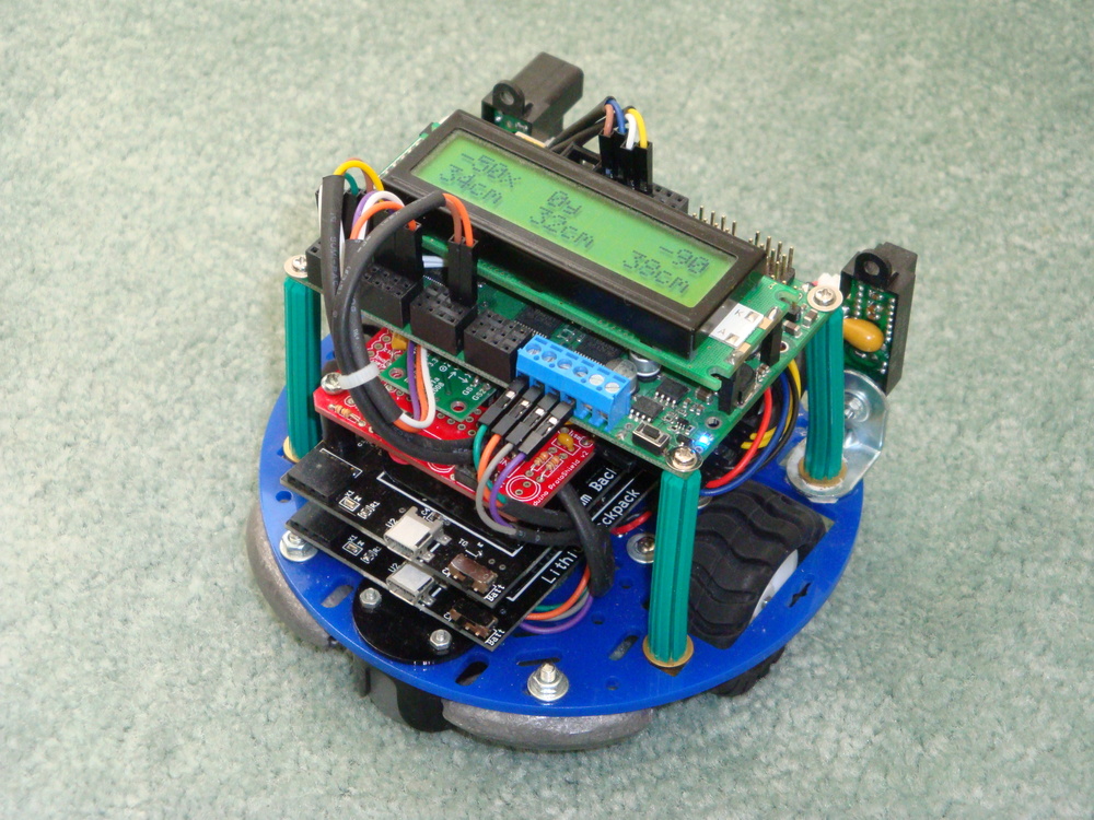
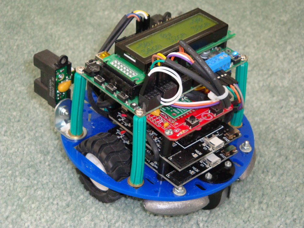
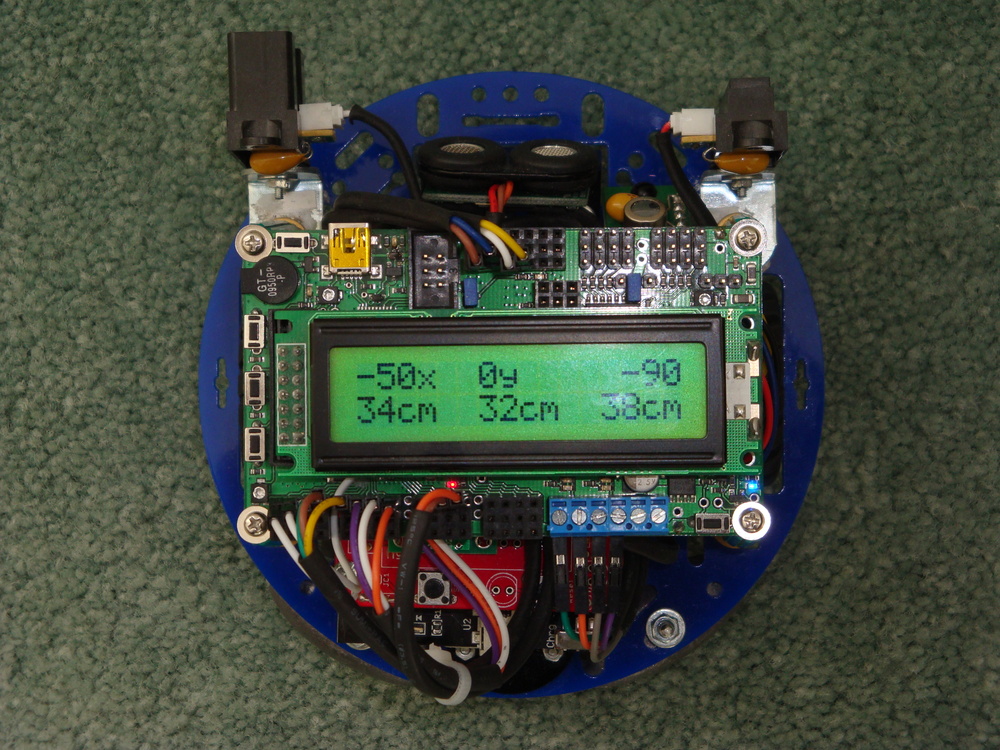
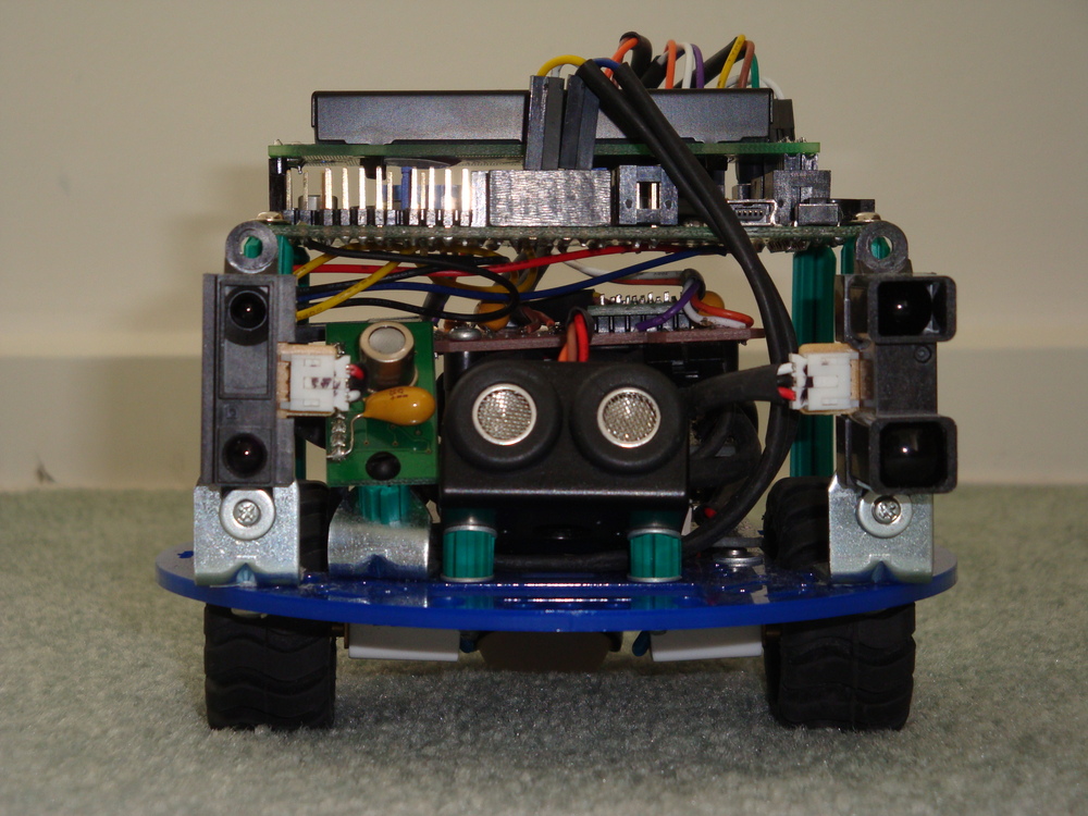
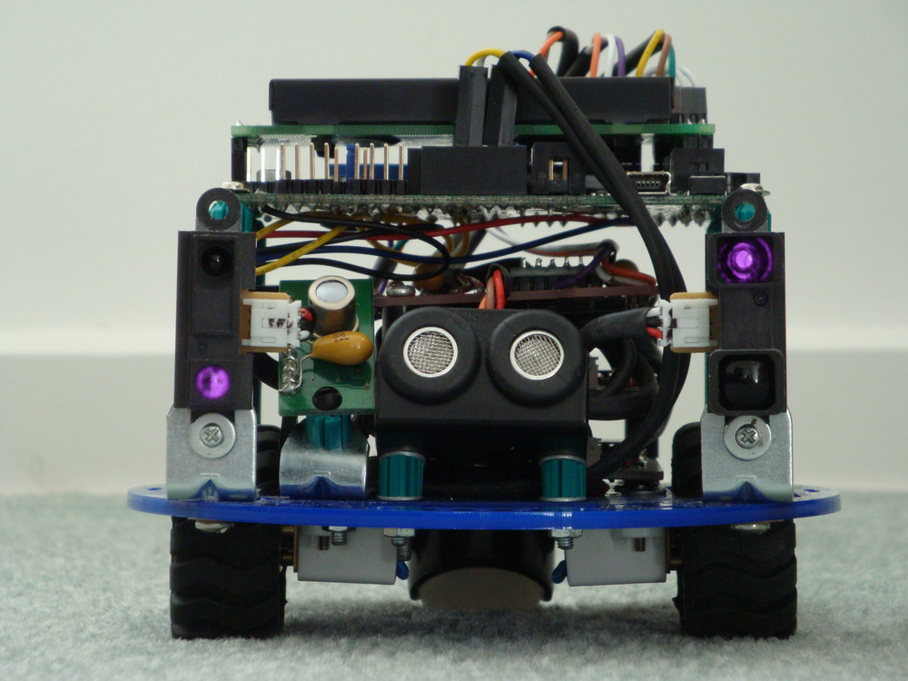
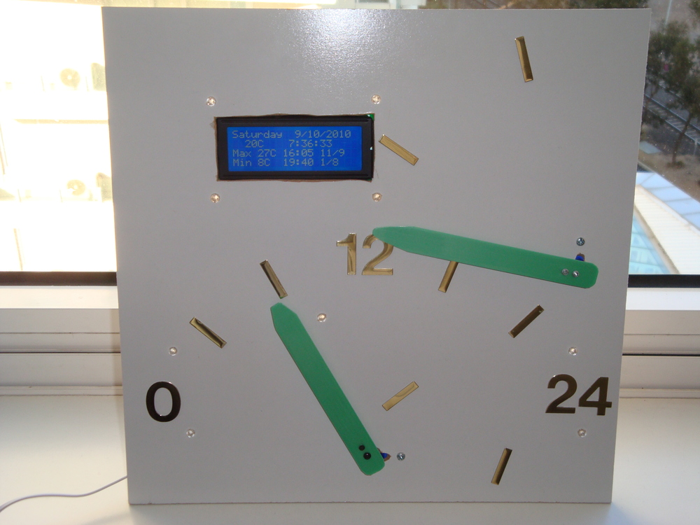
  • Having many finished projects, that are good demonstrations of lots of AVR and freeRTOS capabilities.
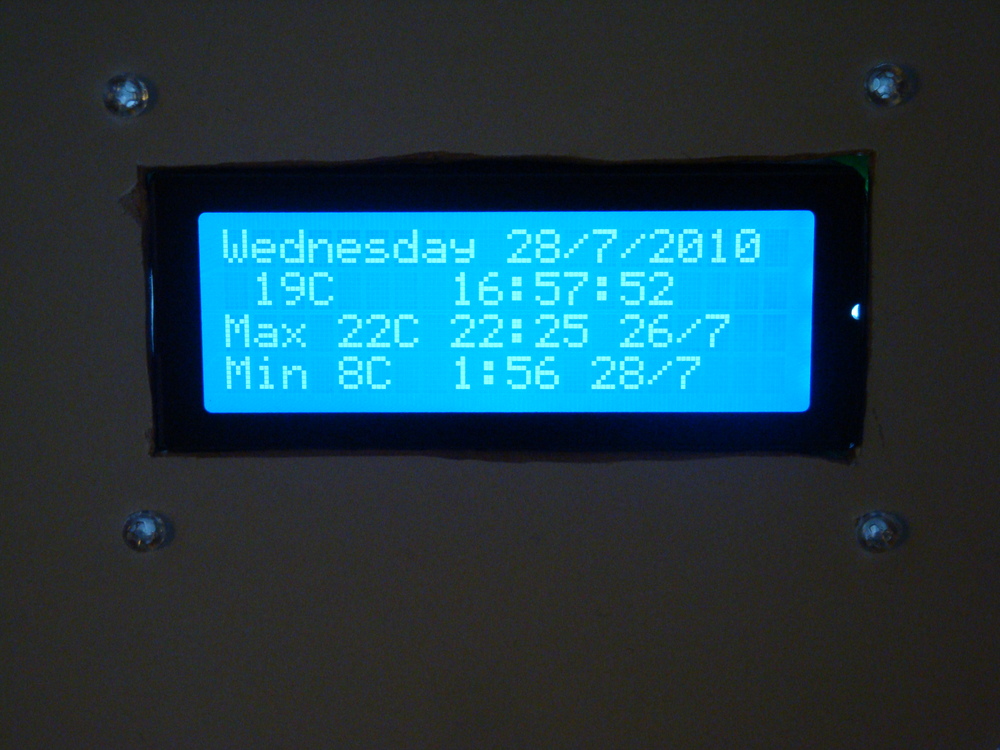
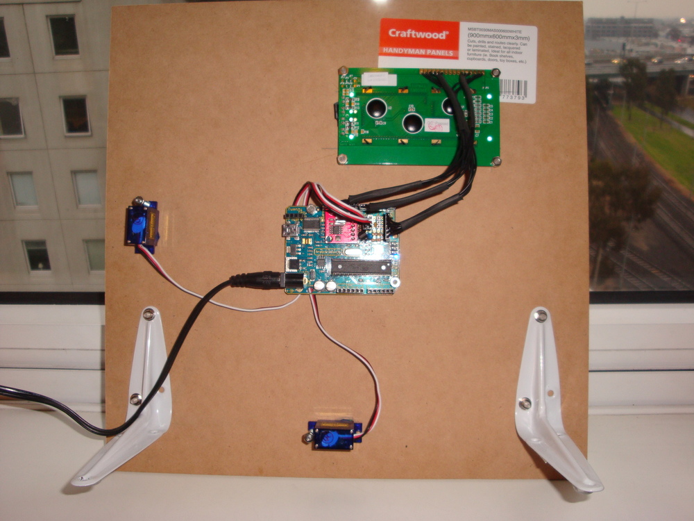
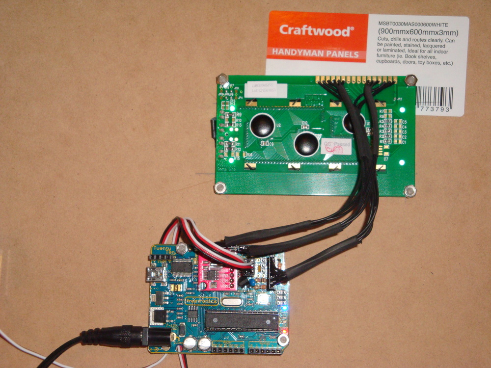
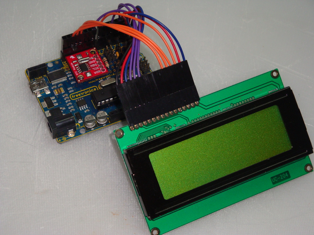
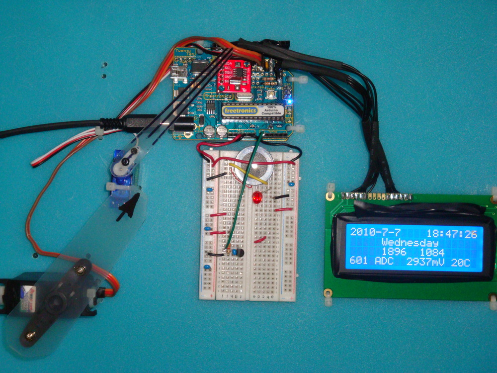
  • Having the Sparkfun LCD Shield working properly, with printf string formatting.
  • Having the Rugged Circuits QuadRAM 512kByte and MegaRAM 128kByte RAM extensions working on ATmega2560.
  • Porting ChaN FatF microSD card support for a variety of uSD shield cages.
  • Porting Wiznet W5100, W5200, and W5500 drivers for Arduino Ethernet shields.
  • Porting Wiznet and uIP DHCP and HTTP applications, creating options for implementing a basic web server.
  • Properly implementing semaphores for access to resources (ports, interfaces, ADC, LCD).
  • Properly implementing queues for transferring data between tasks (threads).

The repository of files on Sourceforge freeRTOS & libraries for AVR ATMEGA is a working collection for a freeRTOS based platform using the AVR-GCC and AVRDUDE platform. The development environment used was Eclipse IDE.

With the Eclipse IDE the C Development Environment (CDE), and the AVR plug-in are both needed. It is assumed that the AVR avr-libc libraries are installed.

The freeRTOS folder contains the most recent version 8.2.3 of freeRTOS, but it has been abridged down to only those files relevant for AVR GCC. The port.c file has been extensively modified to allow the use of either of the 328p Timer0 or Timer1 timers. And, the use of Timer3 on the Pololu SVP which has uses a 1284p. Timer 3 for Arduino Mega using a 2560 also works. Timer2 support has been added for the Freetronics Goldilocks and its 32,768kHz crystal. A Real Time system_tick is added using time.h functionality added to the system libraries described below.

The freeRTOSBoardDefs.h file contains most of the variables that you’ll need to change regularly.

There are some relevant and often used libraries added to the basic freeRTOS capabilities.

  • lib_io: contains often used I/O digital and ADC routines borrowed from Pololu.
  • lib_io: contains the tools to use the TWI (non-trademarked I2C) bus. It contains integrated interrupt driven master and slave routines
  • lib_io: contains the tools to use the SPI bus.
  • lib_io: contains routines to drive the serial interface. there are three versions; avrSerial for use before the freeRTOS scheduler has been enabled, and xSerial for use during normal operations. xSerial is interrupt driven and uses an optimised ring buffer. xSerialN is further generalised to allow multiple simultaneous serial ports.
  • lib_ext_ram: contains routines to drive the Rugged Circuits QuadRam on Arduino Mega2560, or Freetronics EtherMega.
  • lib_util: Optimised CRC calculations.
  • lib_util: Extended alpha (string) to integer (binary, octal, decimal, hexdecimal) conversion.
  • lib_time: Real time calculations, from avr-libc upstream, providing esoteric time and date calculations.
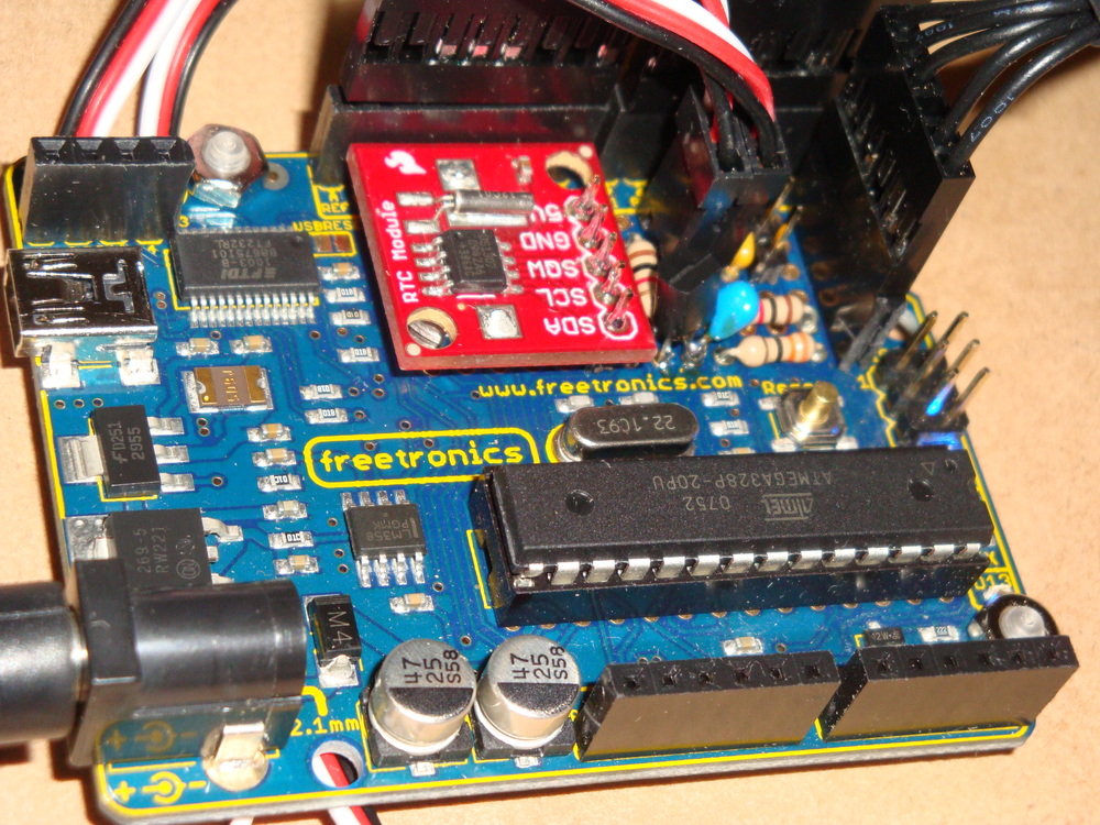
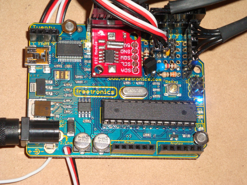
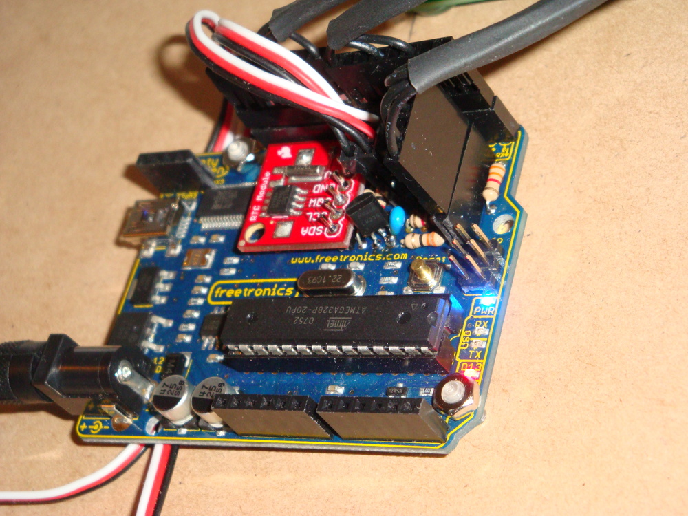
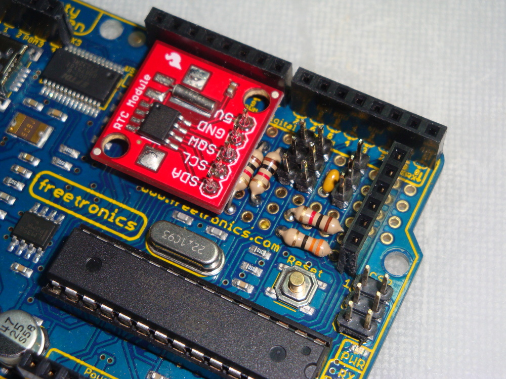
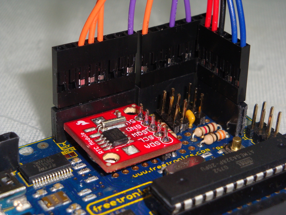
  • lib_rtc: drivers for the DS1307 RTC using I2C.
  • lib_fatf: contains ChaN’s FatF FAT32 libraries for driving the microSD card.
  • lib_iinchip: contains the W5100 drivers and the W5200 drivers from Wiznet.
  • lib_inet: contains a DHCP, and HTTP implementation.
  • lib-uIP: contains the uIP implementation derived from Contiki2.7, implemented on MACRAW mode of W5100/W5200, and extensible.
  • lib_ft800: contains optimised drivers for the Gameduino2, a FTDI FT800 implementation, with LCD and touch screen support.

Some more recent posts are here:

Arduino AVRfreeRTOS

Goldilocks Analogue Synthesiser

Goldilocks Analogue Prototyping 4

Melding freeRTOS with ChaN’s FatF & HD44780 LCD on Freetronics EtherMega

Rugged Circuits QuadRAM on Freetronics EtherMega

Quick review of Freetronics EtherMega

Description of the AVR Pong multi-processor game.

Additional steps to use the Mega2560

EtherMega (Arduino Mega2560) and FreeRTOS

I sell on Tindie

Step-by-step Instructions

Our Destination:

On completing these instructions you should have an Eclipse IDE (Integrated Development Environment) installed with all relevant libraries installed, to use the freeRTOS, and the libraries I’ve modified, to build projects (Eclipse term for a set of code) of your own.

We’re Assuming:

These instructions are based on an Ubuntu LTS install, but the path to the destination is not complex, and can be roughly followed for any installation platform.

Step 0. As usual on an Ubuntu (Debian) system, refresh the software sources.

sudo apt-get update

Step 1. Install the AVR Libraries.

Together, avr-binutils, avr-gcc, and avr-libc form the heart of the Free Software toolchain for the Atmel AVR microcontrollers. They are further accompanied by projects for in-system programming software (uisp, avrdude), simulation (simulavr) and debugging (avr-gdb, AVaRICE).
sudo aptitude install avr-libc avrdude binutils-avr gcc-avr gdb-avr

Step 2. Install the Arduino environment.

Doesn’t hurt to have the Arduino environment available. It can be used for programming boot-loaders (using AVR-ISP code), and generally for checking health of equipment, using known good example code.

This will pull in some extra libraries that the Arduino platform needs.

sudo aptitude install arduino


Step 3. Install the Eclipse IDE.

It is not necessary to use or install an IDE to develop with freeRTOS, or with any other system. It is easy to use makefiles and the command line with avr-gcc and avrdude. In fact, I didn’t use Eclipse for a long time. And, when I first started to use it, it felt very unnatural and clumsy.

However, now I’ve been using it for some time I highly recommend it, for the ability to see deeper into the code (definitions are detailed on mouse over), and to compare (live differences) and roll-back code to any step of your editing process.

Again, installation is easy with Ubuntu (Debian), but it can take a while. Lots of things get installed along with it.

sudo aptitude install eclipse

Step 4. Select the C & C++ development tools within Eclipse.

Eclipse is a Java based platform, but it works just as well with C, and C++, as it does with a wide variety of languages. Getting the C Development Tools (CDT) is the first step to a C environment that we’ll be using.

Open Eclipse, and lock it to your launcher. You’ll be using it frequently.

Using the Menus, click:

Help>>Install New Software…>>Add…

CDT Indigo http://download.eclipse.org/tools/cdt/releases/indigo

Select only “CDT Main Features”, and install these plugin development tools.

Step 5. Select the AVR development environment within Eclipse.

The AVR environment includes direct access to the avrdude downloading tool for one-click programming of your AVR devices.

Using the Menus, click:

Help>>Install New Software…>>Add…

AVR Plugin http://avr-eclipse.sourceforge.net/updatesite/

Select “CDT Optional Features”, and install these plugin development tools.

Step 5c. Select C/C++ Perspective

First you need to select the right perspective, being C/C++. Top right there is a button showing “Java”. Just to the left is a button (like a window) for selecting perspective. Select

Other…>>C/C++

When that is finished, you should have Eclipse menu button containing a AVR* with a green down arrow. That is the button used to program the device.

Step 6. Define a freeRTOS static library project.

There are lots of short cuts, and alternative ways to achieve things using context sensitive menus in Eclipse. I’ll concentrate on the top menu bar options, though you can get most things from a context menu click in the right window.

File>>New>>C Project: AVR Cross Target Static Library: Empty Project

A static library project is never run by itself. It is always linked to by other projects, called AVR Cross Target Applications.

Give the project a name (perhaps freeRTOS82x).

Now a project will apear in the “Project Explorer” window. Select it. We are going to set some options relating to this project.

Project>>Build Configurations>>Set Active>>Release

Project>>Properties

AVR:Target Hardware: MCU Type: ATmega328p (or other depending on hardware)

AVR:Target Hardware: MCU Clock Frequency: 16000000 (for Arduino hardware or other depending on your hardware)

C/C++ Build: Configuration: [All Configurations] (make sure this is set for all following configurations)

C/C++ Build: Environment: AVRTARGETFCPU: 16000000

C/C++ Build: Environment: AVRTARGETMCU: atmega328p

C/C++ Build: Settings: AVR Compiler: Optimisation: Other Optimisation Flags: -ffunction-sections -fdata-sections -mcall-prologues -mrelax (and use -Os or -O2)

Now we are going to add just the freeRTOS files, from the subdirectory within the freeRTOS82x_All_Files.zip file that you have downloaded from Sourceforge, and extracted somewhere sensible.

File>>Import…>>General:File System

Select the “into folder” as the project name you just created, and “Select All” for the import on the freeRTOS subdirectory. That should import the entire freeRTOS system. Spend some time browsing, if you like.

NOTE. Do NOT import the entire contents of the freeRTOS82x_All_Files.zip file. At this stage just import contents of the freeRTOS subdirectory.

Now we define the include library for the build. Remember to select [All Configurations] first.

Project>>Properties>>C/C++ Build>>Settings: AVR Compiler: Directories 

Add the from the “Workspace…”: freeRTOS82x/include

“${workspace_loc:/${ProjName}/include}”

Now there are fouralternative memory management routines, explained in the freeRTOS documentation. We are going to use the heap_2.c version, so we need to exclude the other three files from the build. In the project explorer RIGHT CLICK (context menu) each one then exclude them.

./MemMang/heap_1.c

./MemMang/heap_3.c

./MemMang/heap_4.c

Resource Configurations>>Exclude from Build…: Select All

Following this step, it should be possible to compile the library.

Project>>Build All

If there are any ERRORS, then go back and check the configurations for the project. Sometimes they may be changed, forgotten, or otherwise different from what you expected.

There will be some WARNINGS, relating to the usage of different Timers. I added these warnings to keep these things front of mind, as depending on which hardware I’m using the ./include/FreeRTOSBoardDefs.h file needs to be managed to suit.

Step 7. Define an Application Project.

An Application will generate the final hex code that you upload to the AVR with avrdude. This final code is created from the freeRTOS static library code generated above, together with code contained in the avr-libc, and any other linked projects.

We are going to import the UnoBlink or MegaBlink project as it makes a good example. Without a display, or real-time-clock module, it will only flash a LED. But, least we know it is alive.

To get started create a new project as below.

 File>>New>>C Project: AVR Cross Target Application: Empty Project

Give the project a name (perhaps MegaBlink or retrograde).

Now a project will appear in the “Project Explorer” window. Select it. We are going to set some options relating to this project.

Project>>Build Configurations>>Set Active>>Release

Project>>Properties

AVR:AVRDUDE:Programmer:New…

Configuration name: Arduino or Freetronics 2010

Programmer Hardware: Atmel STK500 Version 1.x firmware

Override default port: /dev/ttyUSB0 (FTDI USB) OR /dev/ttyACM0 (AVR USB)

Override default baudrate: as or if required.

AVR:Target Hardware: MCU Type: ATmega328p (or other depending on hardware)

AVR:Target Hardware: MCU Clock Frequency: 16000000 (or other depending on hardware)

C/C++ Build: Configuration: [All Configurations] (make sure this is set for all following configurations)

C/C++ Build: Environment: AVRTARGETFCPU: 16000000

C/C++ Build: Environment: AVRTARGETMCU: atmega328p

C/C++ Build: Settings: AVR Compiler: Directories: “${workspace_loc:/freeRTOS82x/include}”

C/C++ Build: Settings: AVR Compiler: Optimisation: Other Optimisation Flags: -mcall-prologues -mrelax (and use -Os or -O2)

C/C++ Build: Settings: AVR C Linker: General: Other Arguments -Wl,–gc-sections

C/C++ Build: Settings: AVR C Linker: Libraries: Add “m” without quotes. m is the standard math library, which should be included in most projects.

C/C++ Build: Settings: AVR C Linker: Objects: Other Objects Here you need to add the compiled freeRTOS library. And this is the only place where the Debug and Release builds are different.

With Release Build selected, paste “${workspace_loc:/freeRTOS82x/Release/libfreeRTOS82x.a}”

With Debug Build selected, paste “${workspace_loc:/freeRTOS82x/Debug/libfreeRTOS82x.a}”

Or select the Workspace option to navigate to the actual assembler files to be linked into the project.

Project References: freeRTOS82x ticked.

Now we are going to add the MegaBlink (or retrograde) files, from the MegaBlink.zip (or retrograde.zip) file that you have downloaded from sourceforge, and extracted somewhere sensible. If you downloaded the freeRTOSxxx_All_Files.zip, you have all the sources.

File>>Import…>>General:File System

Select the “into folder” as the project name you just created, and “Select All” for the import. That should import the 2 files shown inro the project file system. Spend some time browsing, if you like.

Following this step, it should be possible to compile and link the project.

Project>>Build All

If this step completes successfully, with no additional ERRORS, then the final step is to upload the new application into your Arduino or Freetronics device.

Make sure that you have your device plugged into the USB port, then simply hit the AVR* button in the row of buttons. You will see some green text showing the status of the upload, finishing with the words

avrdude done. Thank you.

Now, you should have a flashing LED.

Now you can import any additional projects, in the same way.

Step 8. Things to watch.

Turn on the serial port by removing the comments around the serial port definitions, and watch to see aspects of the program in action.

Expect to manage the amount of heap allocated in the ./include/FreeRTOSBoardDefs.h file, to ensure that the total SRAM utilised (as noted in the final linker stage when using heap_1.c, heap_2.c or heap_4.c) remains less than 100% or for ATmega328p 2048 bytes.

Expect to manage the amount of stack space allocated to each task during the set up, to ensure you’re not wasting space, nor (worse) you’re over writing another task’s stack.

For the Arduino Uno, keep the total number of tasks to below 4, otherwise too much SRAM is consumed in stack allocations.

Dogbot – Post 6 – Back on (PID) track

Exactly a year has passed since my last post on the Dogbot. I ended up getting very frustrated with my inability to get sensible odometry out of the Pololu Encoders using the Orangutan SVP auxiliary processor, and needed to put the project aside for a while.

I believe that I spend a good few weeks digging into the code, to see why I wasn’t getting sensible readings from either, or at times both, of the sensors. Then I gave up, and took up an easier challenge being learning PWM control, and started building the Retrograde Clock.

Recently, I picked up the Dogbot again, and determined that I would make it work. I worked out that one of the Encoders was not right, using my excellent new Seeedstudio DSO Nano. So, then I ordered a new Encoder. At the same time I ordered a new chassis for Dogbot, as the old one was damaged by my cleaner, and decided to replace the medium capacity Liquidware Backpack, used for driving the motors, with a high capacity variety.

I took the opportunity to rebuild the dogbot onto the new chassis, and to simplify the system to make it more robust. One construction change was to use the Wall Plugs as a flexible structure, and screw into their ends, rather than using them as a spacer with a bolt through the middle. This allowed me to use the ends of the wall plugs as mounting points, because they could be fastened tight. Previously, because of the angles, they had needed to remain relatively loose.

Dsc04118Dsc04119

I have removed the rear mounted PIR sensor at this stage. It is easy to add again, at the appropriate time.

Dsc04116Dsc04117

Following reconstruction, I found that the Encoders continued to give unusual (wrong) results. Finally, I looked into the details of the encoder outputs again, using the DSO, and realised that their outputs really NEED to be exactly tuned, using the tiny pots, to 50% duty square waves, otherwise the Orangutan SVP cannot get an accurate count. With this fixed, then the Odometry was built up accurately, measuring the count to travel a fixed distance. With this figure, the actual diameter of each wheel can be calculated, and hence the travel required to go in a straight line.

It is important to note, that Dogbot doesn’t go in anything like a straight line, with full power applied to each motor. The friction, and wheel size differ enough to make it curve quickly from the straight and narrow. So PID is absolutely necessary to keep it running straight. With PID implemented properly then, finally, Dogbot runs straight.

These photographs are taken with the display indicating two items. On the top line, the target distance, represented in x and y distance to travel, is noted. Also the deviation from correct heading to target. The instruction is requesting Dogbot to travel 50cm along what it has been told is the x dimension. The instruction is also implying that the Dogbot is initially facing in y direction, and needs to rotate its poise 90deg clockwise to face along x, before it begins its travels.

Dsc04125

The code is set up to all allow specification of an initial poise, and a final poise, as well as x and y distances to travel, for the Transport Task to undertake.

The bottom row of the display shows the distance reading indicated by each of the three sensors across the front of Dogbot. Central indication being the I2C ultrasonic sensor, which is very accurate, but not at all directional. Left being the long range IR sensor, and Right being the medium range IR sensor. These sensors are very directional and can differentiate a thin rod or edge of a hand placed in front of them. Combination of these sensors will enable Dogbot to travel safely in a forward direction.

Not displayed is the output from the I2C thermal sensor. It has been tilted back, so that its vertical array of 8 pixels is looking up from +5deg to +70deg. It can see very small differences in temperature from ambient, which it also reports.

At this stage my work continues to get the Dogbot to consistently travel from one location/poise to another location/poise. Whilst I have the code in a state that it can achieve this, it doesn’t yet do it consistently, because of variables in the drive system that need to be properly tuned. And, I could improve the code a lot too. The code is a bit amateurish.

Notes to photographs

Dsc04122Dsc04121Dsc04124Dsc04123Dsc04127

Liquidware battery packs have a on/charge switch that effectively isolates the battery. This has proven useful, as I can turn the motors off, whilst still programming the Orangutan SVP. Not designed, but in hindsight very useful.

To counter sagging voltages, and noise on the supply lines, I have fitted 1uF Tantalum capacitors on all of the sensors. This helps to ensure that they are getting a good supply when they are firing.

Both Thermal array sensor, and Ultrasonic distance sensor are canted up to get their cone of vision away from the floor. I have left the IR distance sensors facing parallel with the floor, as they don’t get false readings from the floor (assuming it is flat), and I don’t want to miss low objects that might interfere with the Dogbot.

I added the fishing weights to the rear of Dogbot to ensure it had good balance. It has sufficient weight to rear from the batteries to stand up properly, but when braking it is quite top-heavy. So, the low heavy weight at the rear helps to ensure that it doesn’t tip over.

Although there are no other items on the motor circuit, I have added some 1nF bypass capacitors on the motors. Can’t hurt.

It is alive. Here the IR glow from the sensors has been captured by the camera. Perhaps Skynet lives?

Dsc04130

My next steps are to finish the Transport Task so that it can reliably go from point to point. Then, I’ll integrate more information into the Transport task from the accelerometer sensors, to improve directional accuracy. Then to build some mapping code to allow obstacles to be located and avoided.

Freetronics freeRTOS Retrograde Real Time Clock (DS1307) – Part 3 Final

In Part 2  I promised to build a very stylish finished product, that could be displayed with pride. Well, I don’t think I’ve quite achieved that. But, at least now I consider the project finished, and now have the confidence to get on with other projects.

I have mounted some tiny servos, the funky white on blue LCD display, and the Freetronics 2010 board on some Craftwood. Cutting the hole for the LCD was a bit hit & miss, using a carving knife to shape the hole, and managing not to loose any fingers in the process.

Dsc04060Dsc02851

The hour servo is mounted at the bottom of the board, and travels clockwise from midnight, with noon vertical, until it re-tours to 0 on the stroke of midnight. The hour hand travels clockwise from 0 minutes at the bottom, over 30 minutes horizontal, to 59 minutes at the top of the stroke. At 0 minutes, the minute hand re-tours to 0 at the bottom. I find the movement of the servos on the stroke of the hour somewhat like a chime. Not too oppressive, but enough to draw my attention to the passing of another hour.

As the 4 line LCD has so much screen real estate, I have added the maximum and minimum temperature display, with hour, day and month when each extreme was reached.

Adding the LM335Z Temperature IC was discussed in Part 2. I found that the accuracy of the LM335Z IC could be improved by firstly knowing exactly what the Vcc was for operating the AVR device. Measuring this, and putting it in the calculation enabled enough accuracy to be found. Using the 5V regulator on the Freetronics 2010 delivered 4.97V for me, and this value is hard coded into the code. I have several LM335Z devices and they have different offsets, which is adjusted by modifying the subtraction in the Kelvin to Celsius calculation. As the LM335Z is accurate once the offset is established, there is no need to operate it in the “accurate” mode, IMHO, given we have software to make the adjustments it needs.

Dsc02855Dsc02852Dsc02854

The instability in the temperature readings discussed in Part 2 was caused by the long wires to the sensor. Once the device was fixed into the prototyping area on the 2010, together with bypass capacitor, the stability of readings improved greatly. However, during testing, I noted that the maximum values were reading very high. These false high maximum values were caused because the ADC process was sampling during a servo move. The servos consume a lot of power, and this causes voltage drop on Vcc. Hence the reference voltage for the ADC is no longer accurate.

Dsc02845Dsc02847

To prevent the ADC from operating during the servo moves, I simply used one of the freeRTOS semaphores I established previously. I use semaphores to control access to the LCD, the I2C and to the ADC. Use of a semaphore enables independent processes to share a single hardware resource without conflicts developing. The fix for the erroneous high maximums was done simply by taking the ADC semaphore (to prevent the ADC reading process from starting) during times when the servos are being instructed to move. Simple, with freeRTOS to manage the process interaction for me.

ERRATA

The code included in the updated source does not properly fix the issue of false maximum temperatures. It incorrectly releases the ADC semaphore immediately following resetting the PWM values. This means that the hands can still be moving when the ADC process gets unblocked which causes false maximums, because of voltage droop in Vcc, typically at midnight when both hands are in motion.

The fix is to move the vTaskDelay call between the set_PWM_hardware and xSemaphoreGive calls. I also increased it to 2000 milli Seconds too, to ensure the hands are really stopped before the ADC process gets unblocked.

set_PWM_hardware( servoHours_uS, servoMinutes_uS );

vTaskDelay( 2000 / portTICK_RATE_MS ); // a 2 second delay to ensure the hands have properly stopped.

xSemaphoreGive( xADCSemaphore );


END ERRATA

Another piece of code added since Part 2 is to write the maximum and minimum temperatures and the times the extremes occurred into the EEPROM available on the 2010. The functions to use the EEPROM are available in the AVR library and are very straightforward to use. Having a permanent record of temperature extremes is perhaps one thing this clock does, that other clocks in my house can’t do.

There are a lot of comments in the updated freeRTOS Retrograde Clock code, now hosted at Practical Arduino. As a reminder the code uses the AVR and Pololu Libraries, so these both need to be installed before you compile.


Freetronics freeRTOS Retrograde Real Time Clock on PS3 – Part 2a

Just for interest, I decided to see how the support for AVR or Arduino was on the PS3.

Using the standard tools on Ubuntu Lucid 10.4 from my OtherOS installation. A quick search for AVR on synaptic got the avr-lib, avr-gcc, and avrdude tools needed. No special versions, just straight off the repository.

Then, I followed the link to the Pololu Libraries in my Part 2 post, made the changes to OrangutanLCD.h as noted, hit make, and crossed my fingers. No issue. It all worked. sudo make install to put the files in right place.

OK. does the PS3 USB platform recognise the FTDI 232RL USB chip on the Freetronics 2010? Yes. Another hurdle cleared, with no issues.

With that step done, it was simple to download the retrograde files from Practical Arduino as noted in Post 2, extract them. Hit make program and off we go. avrdude works as expected, and the new code is loaded as normal.

I’d say the whole test was over faster than it has taken to type this note.

I should be over this, but I get so happy when technology just works… particularly when it is all free. Got to love your FOSS.

One small issue. There doesn’t seem to be a release of Arduino tools for PS3 (PowerPC). Pity about that. Perhaps in another repository…

Freetronics freeRTOS Retrograde Real Time Clock (DS1307) – Part 2

Part 2 of this project involved learning how to use hardware PWM to control servos. And, then to make the clock actually work with retrograde analogue hands.

First the functional definition. A retrograde movement in horological terms is where the indicators or hands spring back to their home or 0 position at the end of their cycle. So for a minute hand, after 59 minutes and 59 seconds, its next movement would be to reverse move to home at 0 minutes. For the hour hand this could happen after 12 hours or 24 hours. 24 hours is the case that I have chosen to implement. The idea is to have the hour hand trace out a day from sunrise in the east, to vertical noon, and to set in the west.

In part 1, I added the servo headers to align with the Arduino Digital Pins 5 & 6. These pins are driven by the Timer 0 PWM hardware. Following quite a few evenings trying to understand how to generate PWM using the hardware (OK, I’m a bit slow), I realised that it is not very easy to get a good servo signal out of Timer 0 or Timer 2.

To generate the right signal for a servo, you need to produce a pulse every 20mS (50Hz). The width of the pulse should be 1.5mS to get the neutral position. Depending on the servo design, pulses with width from around 0.8mS to around 2.2mS (repeated every 20mS) will drive it to either end of its range. Depending on the servo, 0.8mS may drive it clockwise or anticlockwise. I have both in the clock. For example, the “hour” servo goes clockwise with a wider pulse. The “minute” servo is the reverse case.

The main issue with Timer 0 and Timer 2 is that they are 8 bit timers, counting to 255 before resetting to 0 (ideally after 20mS). Since the required pulses are between 0.8mS and 2.2mS, there are only about 12 “positions” available for the servo to take. Not enough to allow a minute hand to indicate 60 different positions.

Therefore it became clear that, for this application, it was only possible to use the 16 bit Timer 1 to control the servos.

Setting up Timer 1 is relatively easy, once that decision had been made, so the code was implemented. But, this meant that I had to reconnect the servo headers to Arduino Digital Pin 9 and Pin 10, which are driven by the Timer 1 PWM hardware.

Also, in the pictures below, I have added a header to allow power, LCD backlight (32Ohm), and contrast (1kOhm), connections to the standardised HD44780 LCD.

Dsc02787Dsc02791Dsc02789

Ok, so here’s the issue. I’m using the Pololu Libraries for writing to the LCD, and the standard connection for the data line 4 on the HD44780 LCD goes to Arduino Pin 9. The same pin I need for the Timer 1 PWM. Ouch.

Modifying the library is not too difficult. We can move the Data line attached to Pin 9 onto Pin 11, and all is well. This is done in the following file.

~/libpololu-avr/src/OrangutanLCD/OrangutanLCD.h

The changes are noted in the #define lines below

#define LCD_DB4                PORTB3        // Was PORTB1. Use PORTB3 to avoid the Timer1 pins.
#define LCD_DB5                PORTB4        // PB4
#define LCD_DB6                PORTB5        // PB5
#define LCD_DB7                PORTD7        // PD7

//    PortB:     7 6 5 4 3 2 1 0
//  LCD Data:      2 1 0            Use DB3 to avoid Timer1 pins.
//  LCD Data:      2 1     0
//
//  PortD:     7 6 5 4 3 2 1 0
//  LCD Data:  3

#define LCD_PORTB_MASK            ((1 << LCD_DB4) | (1 << LCD_DB5) | (1 << LCD_DB6))  // Modified to avoid using DB1
#define LCD_PORTD_MASK            (1 << LCD_DB7)
#define LCD_PORTB_DATA(data)    ((data & 0x07) << 3)  // Modified the data mask to avoid using DB1
#define LCD_PORTD_DATA(data)    ((data & 0x08) << 4)

The below pictures show the LCD pin layout.
<blockquote”>Red = VCC

Black = GND

BLUE = Voltage for contrast or backlight

Orange = Data lines (4-bit: DB4 – DB7) PB3 (not PB1), PB4, PB5, and PD7. Arduino Digital pins 11 (not 9), 12, 13, and 7

Purple = Control lines (RS, R/W, E) PD2, PB0, and PD4. Arduino Digital pins 2, 8, and 4

Dsc02793Dsc02796

So now we have PWM for our retrograde analogue hands, and a LCD display.

But wait, there’s more…

There’s too much display going to waste, so let’s add something else… Hmm… Temperature, and time, make a min/max thermometer that can show what time each extreme temperature was reached during the day.

Quickly getting a LM335Z temperature sensor, I’m now testing whether the 10bit ADC is good enough to generate reasonable temperature readings from the device. At full range of 5000mV across 1024 levels, we have about 4.88mV per level. The LM355Z produces 10mV per degree, so we should be able to get 0.5 degree accuracy. If everything is perfect.

Currently the temperature gauge works, but the accuracy is still a work in progress, as are the min / max functions. The LM335Z has only two connections, and is biased by a single resistor (3200 Ohm), so it will fit into the board if that is all that is needed. Getting perfection may require addition of decoupling capacitors on AREF and across the sensor, but I’m still
experimenting with this.

Dsc02838Dsc02839

The overall working product is shown below. But wait, there’s more…

I was not happy with using resistors to tie up the SCL and SDA lines high for the I2C bus, as it should be possible to use the internal pull up resistors in some situations (according to the Atmel datasheet).

So using a new Freetronics 2010 from Little Bird Electronics, the clock is now rebuilt without external pull up resistors. The I2C code is modified to only pull up the lines between the start and stop bus instructions. The levels are messy (not showing sharp transitions in my SLO) but, never the less the code and the clock works.

The working device is shown below. Note the rather funky white on blue display I got from Sparkfun.

Dsc02842

In the years since this instruction was writen, I’ve migrated to Github. So the code is hosted here. The freeRTOS code is also posted on Github. I used the Pololu Library for writing to the display, so it needs to be installed along with the normal AVR libraries.

Part 3 will look at how to build a really stylish clock face that can be shown off in public

Freetronics 2010 (Arduino Duemilanova) freeRTOS Real Time Clock (DS1307) – Part 1

I was pondering the blank space on my 2010 recently, and combining that space with some other left over kit from Dogbot, I decided to make a dual retrograde analogue clock.

To build the clock I have the choice of either using NTP to sync a wireless enabled device, or use a RTC clock and re-set it every month or so. For this iteration, I’ve decided to go the RTC route.

Actually, reading this Tronixstuff page also got me going on the idea of using a DS1307 chip, and also Sparkfun makes a nice module that just happens to fit in the vacant space on the 2010. So, I bought one from LittleBird Electronics.

Only other thing to do was to add some servo headers, to get me going with the analogue clock face (using servos).

The picture below shows the layout. I tried a few different options, but this layout seems to only affect the legibility of the pin labelling. Other layouts mask the crystals close together, and I’m not sure how that would affect clock accuracy, or prevent the battery from being removed (9 years later).

Dsc02777

Yes, everything fits. Now to the soldering iron.

Dsc02779

Ok now it is soldered together, and everything looks reasonably fine.

Dsc02780Dsc02781

Now, on the test bed, I have the RTC clock working well using my beloved freeRTOS, and can get on with using the servos to drive analogue hands.

Dsc02785Dsc02784

In the years since this instruction was writen, I’ve migrated to Github. So the code is hosted here. The freeRTOS code is also posted on Github. I used the Pololu Library for writing to the display, so it needs to be installed along with the normal AVR libraries.

Part 2 looks at building the PWM control for the retrograde hands, and adding a temperature function.

Freetronics 2010 (Arduino Duemilanova) Overclocking & Review

Recently, I picked up a Freetronics 2010 from Little Bird Electronics.

Dsc02744

I thought that it would make a nice upgrade to my Dogbot test bed. It uses the same USB connector as Dogbot’s Pololu SVP, so it saves me from keeping different USB cables handy, but is in every way 100% the same as the Arduino Duemilanove that I’ve been using up to now.

But, everything I own is hacked in some way. So as usual, I thought that the 2010 could be improved, just as I’ve improved the Duemilanove before it, by overclocking it to 22.1184MHz.

Overclocking to 22.1184MHz

So why change the clock frequency to this odd number of 22.1184MHZ, and not to 20MHz which would be in specification?

It turns out that because of the binary and integer world the 2010 and the Duemilanova ATmega328p MCU live in, it is much better have a “nice” binary and integer friendly base frequency. Unfortunately, although 16MHz on a 2010 or Arduino sounds nice, from the point of view of integer programming, clock scaling, and UART interfacing, it is difficult to get clean integer numbers.

A small example.
16MHz clock scaled to 115200baud = 138.888888889 so rounding gives an error term.
20MHz clock scaled to 115200baud = 173.6111111111 so, again, rounding gives an error term.
22.1184MHz clock scaled to 115200baud = 192 with no rounding error.

Also, even though we are getting 16,000,000 instructions per second out of a standard?2010, and that should be enough for any application. I can get 22,118,400 or a 38% improvement for the cost of a few cents. So, why wouldn’t you?

What kind of issues can occur?

Well, over-clocking means that the ATmega328p is out of specification. But, I’m not too worried about pushing specification on this project, as the 328p is certified for an industrial operating temperature range, which is way outside of my operating temperature… There are also unverified reports of AVR ATmegas working successfully up to 32MHz.

In the overall scheme of things, raising the clock frequency on the AVR ATmega328p above specification by 10% to 22.1184MHz is no big deal.

Upgrading Process

1. Obtain a 22.1184MHz HC49/US crystal from Digikey They’re pretty cheap. Buy a bag in case of accidents.

Dsc02746Dsc02747

2. Use a knife tip under the existing 16MHz crystal to give you a lever to pressure it into removal, without burning your fingers. It will get very hot!

3. Turn over the board and use a soldering iron to heat the joints, whilst leaning on the knife to lever out the 16MHz crystal. Once it is removed, use some solder wick or similar to remove excess solder, and make it easier to insert and solder the new 22.1184MHz crystal.

Dsc02751Dsc02750Dsc02755

4. Building a new bootloader. In replacing the crystal, the 2010 is effectively bricked. You can no longer communicate with it using the standard bootloader. It is now running too fast and out of specification for avrdude to communicate with it, so we have to compile and burn a new boot loader before we go any further. I choose to use the Adaboot328 bootloader from Ladyada. It resolves a few known issues with Arduino compatible boards, and is easy to compile.

In the ATmegaBOOT_xx8.c file, change the UART baud rate to 115200, if you use avrdude for programming (if using Arduino IDE, do not change this from 19200). Who has time to wait around these days for 19200 baud, anyway?

/* set the UART baud rate */
#define BAUD_RATE?? 115200

In the Makefile, change the AVR_FREQ value to 22118400L for the adaboot328: TARGET.

adaboot328: TARGET = adaboot328
# Change clock frequency from 16000000L
adaboot328: AVR_FREQ = 22118400L

Then, compile the bootloader, and keep it safe.

5. Prepare an ISP. There are many alternative ways to do this, and here is not the place to describe the alternatives. Suffice to say that I used the AVRISP method in the Arduino-0018 IDE. I’ve struggled with avrdude (which I otherwise use for everything) as a bootloader ISP. I don’t know why, but I can’t make it work.

It happens that I have a standard Arduino clone available, which I prepare as the AVRISP, by uploading the following sketch File>Examples>ArduinoISP.

6. To be able to use Arduino IDE to burn our special bootloader, you have to replace the standard ATmegaBOOT_168_atmega328.hex bootloader file, found in ~arduino/bootloaders/atmega/ with our newly generated file. And, to make things simple, I just rename or remove the standard one, and replace it with our newly prepared and renamed bootloader with this name
ATmegaBOOT_168_atmega328.hex.

7. Connect our Freetronics 2010 up using the AVRISP connections, described on the Arduino web site. Make sure we have the right board type selected; it should be Duemilanova w/ ATmega328. Then using the Arduino IDE use Tools > Burn Bootloader > w/ Arduino as ISP.

Dsc02756

8. Program a sketch using either the Arduino IDE, or using avrdude, remembering that the baudrate is set to 115200. And, enjoy.

Conclusions regarding the Freetronics 2010.

Its a very well designed and produced device, that is 100% compatible with the Arduino Duemilanova. Some advantages are: the mounting holes are slightly larger so cable ties go through nicely, smaller USB connector is more common than the B connector used on Duemilanova, and there’s no solder in the holes for the X3 connector so it is easy to add headers to make it possible to burn its own bootloader (if you want).

It runs my freeRTOS build with no problems, as seen in this demo on my Dogbot test bed with a Robot Electronics Thermopile, and Sharp IR Distance sensor.

Dsc02760Dsc02761

DogBot – Post 5

So some time has passed and I’ve had some success with different aspects of my robot.

For simplicity, I’m using a test bed based on an Arduino Duemilianova connected to a Nerdkits sourced display. I’ve hooked the display up as if it was a Pololu Orangutan SV-328 and am using Pololu libraries to write to it. Also, I’ve been working on the actual SVP based robot, so both of which are working well.

The processor 328p is used for the Duemilianova and requires the use of the Timer0, which implies no Pololu motor library code is possible without conflicts. However this is not an issue, as the Duemilianova doesn’t have motor drives anyway. The actual DogBot has the 1284p which is used in the SVP and uses Timer3, which has no limitations on any known libraries to my knowledge.

The freeRTOS code is posted on the Pololu Forum, mostly just back-up as the application code is very immature.

At  this stage I’ve got all of the I2C bus based sensors working, based on code developed by Fleury. So, I can read the thermal sensor for its 8 pixels, and equally importantly, I can read the SRT10 Ultrasonic Sensor for distance in cm. One issue with the ultrasonic sensor is that its field of vision is so great that it basically detects anything “in front” of it. Good to not run into things, but pretty useless as a fine directional capability. It seems lucky that the Sharp IR distance sensors are very directional, and sufficiently accurate as a complement. The analog sensor readings are working well too, though I still have to create a ADC to cm regression.

From the point of view of sensing, it looks like the Sharp IR sensors will be the reference. With the SRT10 sonar being most relevant to create a “zone of safety” where I can be assured that the nearest object in a cone of 120deg is measured, but can’t be sure exactly which direction the object is. On the thermal side, I will get a vector (direction and temperature) from the sensing location, but no distance. But, that I knew and expected.

Putting some effort into designing the motor control, or Transport Task, has taken up my thoughts recently. I don’t want to link the odometry available from the quadrature encoders back into the mapping or routing task. Similarly, I don’t want to link the intertial navigation available from yaw and linear acceleration sensors into the motor task.

I think the transport task should simply take a vector,  relative to the the current pose of the robot, and execute these translation commands subject to feedback from odometry, leaving the inertial navigation to another task.

This fits well into the design of the hardware, as odometry can can be queried from the Pololu SVP ancillary processor, without blocking, and the motor PWM drivers can be also managed without blocking other tasks. This creates a self contained task that does not need to share resources with other tasks.

However, the inertial sensors are analogue readings and the ADC will need to be shared with the Sharp IR distances sensors. Creating the need for a semaphore, and blocking based on the availability of the ADC.

Because of the battery issues described in Post 4, I’ve had to remove the servo neck of the DogBot. Therefore, I will implement the option for motion to be along circular paths, as well as along a straight line. Motion along a straight line, with stationary rotations to create the correct pose prior to departure, are the best paths to arrive at the destination with the lowest risk and shortest path. However, with a fixed sensor head, straight lines don’t fill the map with information as they leave the sensors always pointing in the same direction.

If the DogBot proceeds from A to B via a circular route (if this is requested by the mapping or logistics task), then the sensors will be pointed at all directions from +90 to -90 degrees along the path to the destination. Allowing the travel time to be used effectively for data acquisition.

If I’m feeling smart, then I can create any number of route subdivisions, and force DogBot to describe a path of smooth semicircles to the destination, gathering sensor data along the route.

The inertial sensors can be run in a parallel task (using the ADC along with the Sharp IR sensors), with the odometry (from the ancillary processor) to cross check that the expected distances and directions are traveled. Whilst I think the odometry is more likely to be accurate, the map will be updated constantly so some inaccuracy should be expected and tolerated by the code.

My next step is to design this transport task. This task should take distance, bearing and path description (straight line, circle, sinusoidal, etc) and carry it out to the best of its ability (odometry PID data only). I expect resolving this effort will take the next few weeks, and perhaps longer.

Later work is to develop the logistics and routing task that will issue the navigation requests to the transport task.

Continued with Post 6 (one year later).

Dogbot – Post 4 – Hardware & freeRTOS Complete

Ok so some time later, I’ve finished building up the hardware.

It is basically a 4 level stack, with the two Li batteries on the bottom, followed by a proto board which carries the acceleration sensors, and distributes power and signal lines.

The top level is the Pololu SVP and its daughter display card (level 5).

25742_419162736067_610931067_5621385_2222535_n
25742_419162646067_610931067_5621384_4844593_n
25742_419162756067_610931067_5621386_5021337_n
25742_419162776067_610931067_5621388_4697390_n
25742_419162806067_610931067_5621389_6666628_n
25742_419162876067_610931067_5621390_4382446_n

What issues are there?

Well electrically none. All the signals are working perfectly, as demonstrated by the Pololu Analogue and Digital code, together with their motor and servo code. All the hardware seems to be functioning perfectly.

But, there are some problems.

The Li battery packs are incapable of providing enough current. I should have done a power budget before building. Everything works pretty well, although there is some voltage droop to 4.5V, until I turn on the neck servo. Then Vcc drops to 3.5V and the DogBot dies.

So the choices are to remove the servo, and program the scanning function using the body, or build a new boost power supply. At this stage I’m tending to think it would be better to just remove the neck servo, and use the chassis for scanning.

Also finished is the freeRTOS port, using Timer3 from the Atmel MegaAT1284, which is not found on other devices of this type. This allows me to have no conflicts with previously written code (using Timer0, Timer1, or Timer2). However, I will still need to go through all libraries to ensure that they don’t cause problems by being interrupted by the RTOS.

So now onto some heavy system design to work out exactly how to implement the mapping and searching functions, and how to drive in a straight line.