Yet Another Z180 (YAZ180 v2)

Testing on the YAZ180 v1 , shown below, is now complete. I don’t want to use it for further driver and platform development, because the PLCC socket for the 256kB Flash is becoming worn-out.

It will continue to operate as an augmented Nascom Basic machine, with an integrated Intel HEX loader (HexLoadr) supporting direct loaded assembler or C applications.
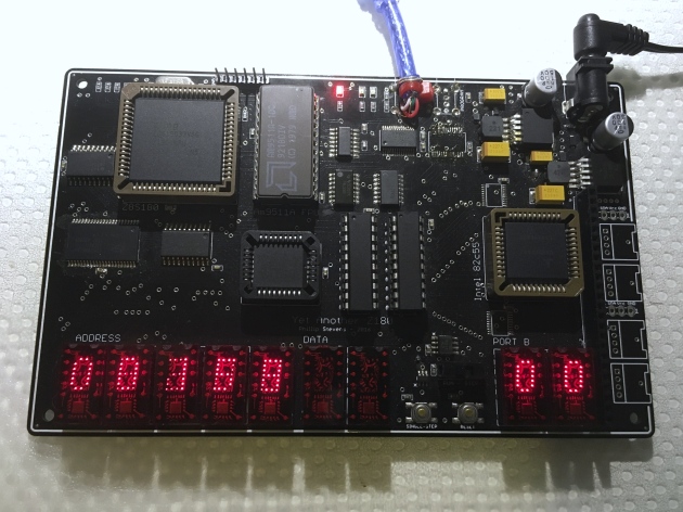
img_0626

YAZ180 v1 at full configuration.

The new PCB for the YAZ180 v2 has been ordered.

These are some screenshots of the new PCB.


Update

Pi Day, March 14 2017.

After dwelling on the fact that the V2 PCB was really just a clean up the V1 PCB, with no additional features, I decided not to build the beautiful new PCBs that arrived today.

But rather, to create a new PCB with additional features.


New Features

When I originally designed the YAZ180 the breakout for the 82C55 was simply an interim design, to enable me to test the board. I was thinking of making an Arduino style pin-out, or something along those lines. But this is something much better.

Recently, after reading Paul’s page on interfacing an IDE drive to an 8051 microprocessor with the 82C55, I decided that adding IDE to the YAZ180 was a must-have feature.

So there is a new connector on the YAZ180 to break out the 82C55 pins, in IDE 44-pin 2mm format. I have not followed the design provided by Paul exactly. I’d note that his design and the earlier design by Peter Fraasse were specialist designs, which don’t support the generalised usage of the 82C55 chip, beyond the IDE functionality.

By the above statement I mean that in Mode 1 and Mode 2 for Port A and Port B, the PC2, PC4, and PC6 pins of the 82C55 device are designated registered strobe input pins /STB in input mode, or peripheral acknowledge /ACK in output mode. If an inverting output buffer is connected on these lines, then the registered input and output mode capability is lost. This would restrict the functionality of the 82C55 to simply Mode 0, being the mode that is used to create the IDE functionality.

As I’ve connected the three IDE address selection pins to PC2, PC4, and PC6, and these pins are not passed through an inverting buffer in the design, it is possible to use the 82C55 in any of its modes, and therefore to use the IDE 2.5″ 44-pin form factor to connect the YAZ180 82C55 ports to extension PCBs of any type or design.

As a connected IDE drive or other extension board may need to interrupt the CPU, I have connected the IDE INTRQ pin to the remaining inverting buffer to provide an input to the CPU on /INT0. As the /INT0 (or actually the INTRQ) input terminates on the IDE header, either a IDE drive through INTRQ, or either of the two 82C55 INTR pins, PC3 or PC0, can originate the interrupt.

I have reconfigured the Am9511A-1 to use the /NMI interrupt, as previously the /INT0 was configured.

The new YAZ180 v2 PCB has been ordered. YAZ180_v2_Schematic.

Happy Pi Day.

Update – RetroChallenge Day 1

I’ve decided to enter the RetroChallenge 2017/04 and my challenge is to read and write to an IDE drive using the newly configured IDE interface on the YAZ180v2. But before I can write the code for the IDE interface, there’s a bit of building and testing that needs to be done.

The new PCBs arrived a few days ago, and they look great. But Arduino Day and the first day of the RetroChallenge 2017/04, 1st April, seemed like a good day to lay them out.
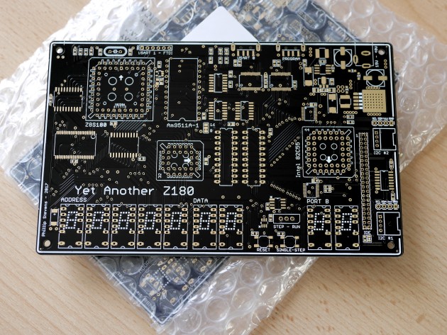
P1080754

New PCBs. 2oz Copper, 2mm thick. Opulent.

I was hoping to lay build several boards at once, but somehow I forgot that there was only one RAM and one FT245 device in my component stocks. That means that I had to satisfy myself with just one board for now.

Note the suitably Retro PowerMac (circa 2001) driving the layout guide screen.
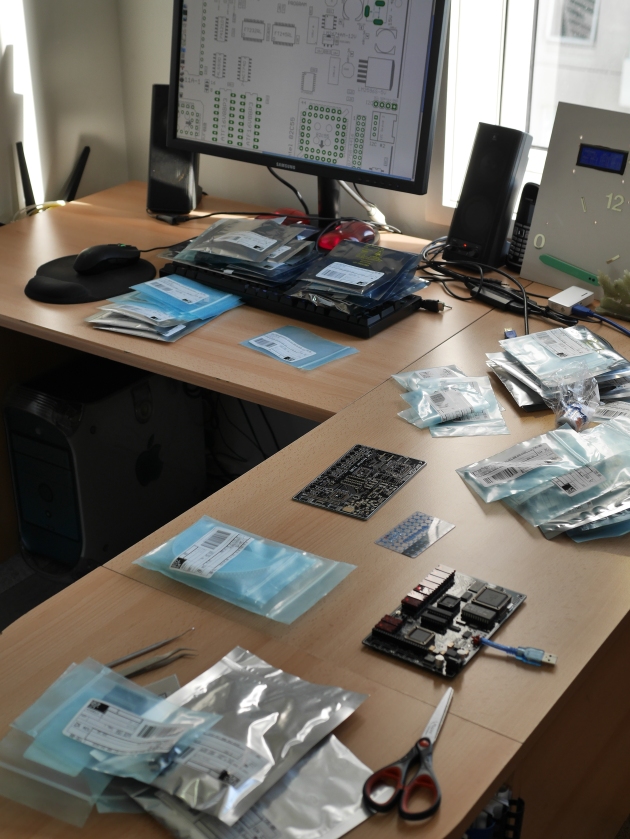
P1080755

Adhoc Workspace

This is the board just before cooking. Respect to anyone who notices the substantial noob layout mistake. Anyway, after a small smokey explosion, everything was rectified.
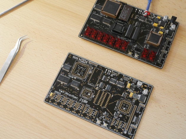
P1080758

Two YAZ180 versions, side by side.

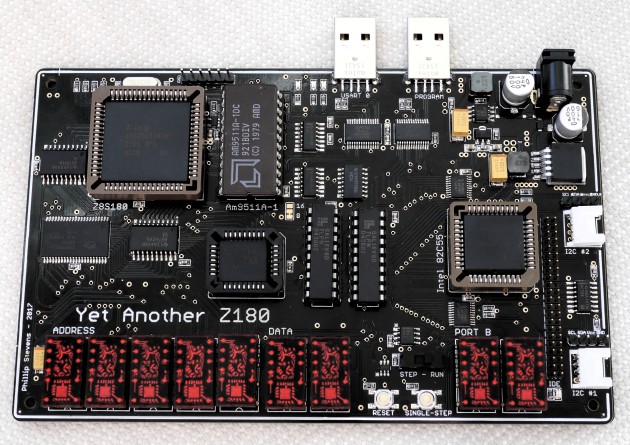
This is the finished build of the YAZ180 v2. Looks very tasty. Retro goodness.
P1080761.JPG

Fully populated YAZ180 v2 PCB.

I’m still working on fixing an issue with my code, which I noticed when experimenting with the Am9511A APU, and inserting an Interrupt Jump Table. Basically, I’m getting jumps to odd or  random locations, which is detected buy filling unused locations with 0x76, the HALT, OpCode. The most common address where the HALT is executed at is 0x00C3.

Previously, I’d been filling unused locations with 0xFF, the RST 38H OpCode shared with the INT0 location 0x0038, which was causing the APU to be triggered inappropriately. This issue has me snookered. I can’t move on, in the software sense, until it is resolved .


This slideshow requires JavaScript.

Update – RetroChallenge Day 8

Well this week was one of the most frustrating weeks ever, in terms of time spent vs. results obtained.

There are two major projects in hand. 1. Getting the YAZ180 v2 running, and 2. resolving the software issue plaguing my initialisation code.

Hardware issues

Bringing up a new piece of hardware is never easy. Initially, nothing can be trusted to work, and everything needs to be checked against the design, and then even the design checked for correctness. Bringing up the YAZ180 v1 was very time consuming, because I had to develop the PLD design during the process, as well as checking that all the hardware was sorking as it should. I thought that bringing up the YAZ180 v2 would be easy. Just solder it together and win. But it has not been so simple.

Essentially, after a week of working on this every evening, I don’t know why it is not working correctly. All the standard things, volts, clock, stuck address and data lines, etc are all working correctly. But it still doesn’t work. And, it may not be just one thing that is wrong, but if anything is not perfect it just won’t work.

After a few days of testing, I found that I’d programmed the PLD devices with an old version of the CUPL code. Nearly right, but not exactly right. Once I’d isolated that issue, by ensuring the new GAL devices worked perfectly in the V1 board, I thought it would be enough. But no. There’s still something wrong.

My current thought is that somehow, either electro-static damage or heat damage, the RAM is unreliable. But, I’m not sure enough of this to unsolder the RAM device and replace it. I’ll be spending this weekend on resolving this problem.

Software issues

Because of the effort I’ve been putting into resolving the hardware issues, I’ve not been able to solve the software issue apparent in the YAZ180 initialisation and serial code. I’ve documented the issue on Github.

My lesson learned is NOT to fill unused memory with 0xFF bytes. This causes RST 38H jumps to the INT0 location when the PC is incorrectly loaded, and can be very distracting. Best to fill unused memory with either 0x76 HALT bytes, to see where things became broken, or with 0xC9 RET bytes to just float over the underlying issue.

I’ll need to fix this properly, but it has consumed several weeks of effort, and I’m not much closer to resolution.

Update – RetroChallenge Day 10

The weekend was unkind, but today some new eyes (literally) have brought successes.

Hardware Issues

After doing quite a bit of further testing, I’m fairly sure that I’ve damaged the RAM and will need to replace it. So, I’ve ordered a hot-air solder gun. Should have had one for a long time. Finally, I’ve got a round-‘tuit. I’ll have to order some replacement components too, which will result in being able to make additional boards as well.

Software Issues

Finally, I’ve resolved my issue. What we had here was a classic “failure to understand”. Somewhat embarrassed to leave this here for Internet eternity.

  • Z80 vectors are supported by a JUMP table.
  • Z180 vectors are supported by an ADDRESS table.

Insert JP instructions into an address table and you will have a very very bad day.

Or in my case, quite a few of them.

This issue cost so much time. But at least on the up side, I’ve written robust Z80 and Z180 vector tables, improved my ASCI code, and cleaned up initialisation code, in trying to track this down.

Also finally, I now understand. Which is the entire point, anyway.

Update – RetroChallenge Day 17

Following up on the success of last weekend, I was hoping to have a lot of achievement to write about today. Unfortunately, it has been a grind this week too.

I have been distracted back into the original project that unearthed my previous software problem, and led me along the path to getting a much better understanding of the Z180 CPU, and then solving the issue. The original project was building an interrupt driven driver for the Am9511A-1 Arithmetic Processing Unit.

I’ve spent pretty much the past week on this code, and digging through it with a fine tooth comb. I’m now of a belief that my Am9511A driver code is correct, but my hardware is not correct and may never be correct.

The issue lies with the requirement for the Am9511A to have the Address lines and Chip Select signal remain valid for 30ns following raising of the Write signal. Unfortunately, the Z180 only maintains valid address lines for 5ns following Write. This means that writing to the AM9511A APU is very much a hit and miss affair, with miss being the most likely outcome. I’m still thinking about ways to bodge this to work. But, I think that it may just be too hard to get the old APU to work with a modern CPU. More on this later.

This week I’ll be working on the PaulMon IDE code, and migrating it from 8051 to Z80 nomenclature, and trying to get it to compile.

Update – RetroChallenge Day 21

Well the last couple of days have been exciting, as I found a way to make the Am9511A APU work. A hint from a fellow competitor (on working with the MC6809 CPU) inspired me to look further for information on options to fix the hardware interface.

The Z180 E CLOCK

The Z180 has an almost undocumented feature, called the E Clock. Yes, it is documented in datasheet that it exists, but there’s no real background that I can find as to why it exists, except that is for a Secondary Bus Interface. This pin and signal doesn’t exist on the Z80, for example. Anyway, since it has the same name as a signal on the MC6809, I thought it might be worth looking at it. It turns out that the E Clock provides a shortened version of the WR and RD cycles. Which is exactly what we need.

One caveat however, when running at doubled PHI rates (i.e. 1:1 PHI – CLK) the shortening of the E Clock signal is not sufficient to drive the APU successfully. At 18.432MHz, the PHI/2 timing is 27ns. Therefore, the minimum of 30ns between release of WR and CS is not always held. This means that we’ll need to keep the PHI at half CLK whilst using writing data into the APU. In practice this means that using the APU requires we cut the CPU clock by 50% or PHI/2 being 57ns, to ensure the trailing 30ns is provided.

Anyway. Good news. With the revised timing, the Am9511A-1 is working.
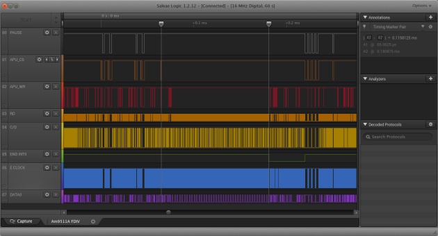
Am9511A FDIV

Am9511A APU Floating Divide in 115us

The E Clock is not an inverted signal, so to generate the active low APU_WR signal we have to first invert it, then OR it with the WR signal. For the purposes of testing, I’ve got a little breadboard with a GAL on the side, but later I’ll build a new PCB and add in a SN74LVC1G97 little logic device to provide the APU_WR signal.

Am9511A FDIV PUPI

Am9511A APU FDIV PUPI command interval 128us
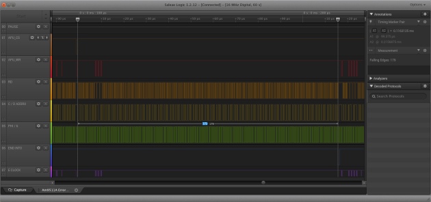
Am9511A FDIV PHI6 Cycles

Am9511A APU FDIV in 179 Phi/6 Clock cycles

So now we see the Am9511A APU FDIV floating point divide takes about 101us to 115us when running at 1.536MHz, or from the datasheet 154 to 184 clock cycles. In 101us, the Z180 CPU at 36.864MHz produces 3,723 cycles. To produce a floating point divide using the Lawrence Livermore Library requires about 13,080 cycles, according to the AM9511A Floating Point Processor Manual by Steven Cheng. Therefore, we are still substantially faster than antique software on a modern Z180!

Update – RetroChallenge Wrap Up

Well the month of RC2017/04 didn’t go quite as planned. My original intention was to have the YAZ180v2 working very quickly, then get straight down to porting Paul’s IDE code from 8051 to Z180 to get the new IDE interface working. But, there were several speed bumps along the way.

Gaining an education

Since I just started on this whole Z80 processor and assembly language programming thing a few months ago, I don’t have a long history of coding to fall back on. I had written some code for the Z80 in the RC2014 hardware, which I then tried to use on the Z180 in the YAZ180. But, there is a subtle difference in “generation” between the way the interrupt vectors work across the two machines. Obvious, once you know about it but a real “time killer” if you don’t.

Firstly, filling unused space in your assembly program with 0xFF is a very dangerous thing to do in Z80 assembler, particularly if you don’t understand that 0xFF is the op code for RST38, which is a single byte jump to the same location as the Interrupt 0 in IM1 mode. It would make more sense to fill the unused space with 0x76, which is the HALT instruction, to trap an unexpected program counter value.

Look before you leap

Secondly, the interrupt vectors on the Z80 were designed to contain code, and the PC is just loaded with the address of the vector, and execution begins from there. So for an INT0 (or RST38) execution begins from 0x0038. But, the interrupt vectors on the Z180 are designed to hold an address. The difference being that an interrupt will load the PC with the contents of the two bytes at the vector, and then begin execution from there. I think this difference is a sign of the generational difference between the two implementations. One of the clearest differences I can find, anyway.

Timing is everything

One of the goals for the YAZ180 is to bring some old chips back to life, in a modern platform. Along with the TIL311, GAL16v8, and 82C55 devices, the Am9511A holds pride of place as the very first arithmetic processing unit ever made. I’ve invested far too much time in getting the Am9511A to work, but it is important to me that my project can make it work.

I believed that I had devices that were specified to run at 3MHz but which in fact didn’t. That may be incorrect. More likely was that I wasn’t driving them properly, because my timing was out. I will need to go back and test them all again.

Here the issue is that the Am9511A requires extended validity of data and chip select signal, following the validity of the write signal. At least 30ns is required. This is not provided by the Z180 in its normal timing, although in the configuration I have it, coincidentally because I’d buffered the data bus, it is nearly right. Only the chip select line was being incorrectly handled.

I was nearly giving up but then a tweet from a fellow RC2017/04 competitor gave me the inspiration to look further. It turns out that the Z180 has a secondary I/O timing signal called the E Clock. This signal is not present on the Z80, and as I didn’t understand its purpose I’d left it unconnected in the YAZ180.

Whilst the Zilog datasheets on the Z180 completely gloss over the purpose of the E Clock signal, by simply not mentioning it, the original Hitachi 64180 datasheets do mention it. The original purpose of the E Clock signal was to provide timing for “a large selection of 6800 type peripheral devices” including the “Hitachi 6300 CMOS series (6221 PIA, 6350 ACIA, etc) as well as the 6500 family devices”.

In summary, the E Clock provides a signal that is half a T cycle shorter than the write signal. It means that gating the write signal with the E Clock would allow me to release the APU write signal sufficiently early to maintain the extended chip select timing required. Basically, the APU won’t operate with a Z180 T Cycle any less than 60ns, or 16.6MHz. So in my implementation, the PHI clock will need to run at half speed or 9.234MHz, whilst the Z180 is using the Am9511A. Unless I cook up another plan.

Zapped

And the final note from this month is that I believe my very poor ESD protocol has led to the destruction of the SRAM on my YAZ180v2. Therefore I had to desolder it (and it looked so nicely done) to remove it, and order some new components.

Ordering new components is always a bit of a hurdle for me. I’ve collected quite a few things that I don’t use, so I tend to ration myself on purchases vs. progress. Finally, at the end of the month I ordered more components to build further YAZ180 boards, and some spare SRAM to enable me to repair the one I have made already.

It continues to amaze me just how much difference there is in the cost to build an Arduino AVR board (basically just a chip at the most essential level), vs something like the YAZ180. The YAZ180v2 bill of materials, excluding specials like the GAL16V8D, TIL311, and Am9511A devices that I have to find of eBay, comes to over $150 Australian!!! We need to export more coal, to get the AUD dollar back up there!

And that’s it for my RC2017/04 month. Soon as the parts arrive I’ll be completing the YAZ180v2, and then testing the IDE interface. I hope that will be done before the end of 2017/05.

Update – Post RetroChallenge

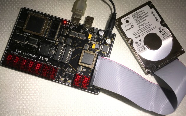
Well good news. The only issue was a bad solder joint on the new SRAM chip. Now the YAZ180v2 is running, and I can get onto translating the IDE code from 8051 to Z80.
IMG_0698

YAZ180 with IDE drive attached.

I’ve sourced code from both PJRC in 8051 mnemonics for an 8255 PIO and from Retroleum in Z80 mnemonics for an 8 bit interface. Between the two of them, together with the examples from the OSDev Wiki, it should be easy to make a fairly robust implementation. And, on May 18th, the driver code was finally working.

Next activity is to integrate this into the z88dk, and then using the FAT-FS code from Elm ChaN, get the disks properly working.

Update – August 2017

Over the past few months progress has been made on various fronts with the YAZ180v2. Firstly, the IDE interface is fully working, and has been integrated into z88dk. Also, the issues with the Am9511A-1 APU have been resolved, and a working driver has been integrated into z88dk. While I still have to revise the C interface for these two pieces of code, because I’m still learning this, the development work is now done.

I am particuarly happy about getting the Am9511A APU working, as this was causing me the most technical difficulty, and stretched my understanding the most. I’m also happy that the capability in the Am9511A seems to be realised through performance improvements in arithmetic computation.

Over the coming months, I hope to resolve the remaining untested components in the YAZ180. These include the parallel programming interface, to allow the YAZ180 to be “cold loaded”, to protect against bricking the system, if a user doesn’t have a EEPROM or Flash writer. I’m still in two minds abou this feature, as the cost of the FT245 device and USB socket is about the same as a stand alone EEPROM writer, and the parallel programming interface consumes space that could be otherwise used for an SPI or USB interface, for example.

I also need to test the I2C interfaces, and debug the driver that I wrote back in May (still unused) to complete the feature set.

With this done, I’ve now done a new minor revision of the hardware, to clean up the issues that have been noted over the past months.

Open Issues

  • APU – Gate E clock with WR to produce shortened APU WR
  • NMI – remove this from the APU, and terminate high. Not CP/M compatible.
  • INTO – reconnect it to the APU.
  • 5V – Power inductor spacing.

Update – October 2017

Well, I fixed the issues and then convinced myself that there needed to be Yet Another feature added to the YAZ180, before I signed it off. So now, the v2.1 board has access to the Internet through an ESP-01S AT interface.


This slideshow requires JavaScript.

I sell on Tindie

Building up this new board will be November and December’s activity, together with building a complete YABIOS (Yet Another BIOS) to make use of all of the features packed into the YAZ180 board. I’ll be picking the best bits, IMHO, from the Cambridge Z88, ZX Spectrum, and CP/M 2.2 – ZSystem to build a banking capable YABIOS, supporting 1MByte of address space.

Update – August 2018

I seriously need to write another blog on the YAZ180. But I guess the Github commits just speak for themselves. There are only three things left on the to-do list. 1. finish the firmware loading program. 2. rewrite the I2C interface. And 3. implement FreeRTOS as a hypervisor allowing multiple 60kB applications to run simultaneously.

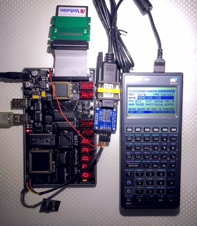
Here’s a picture of an application, which was one of the early drivers for building the YAZ180, a mass-storage platform for my HP48 calculator.
IMG_1572

YAZ180 communicating with HP48 using Kermit on ASCI1 (TTY).

Arduino FreeRTOS

Arduino FreeRTOS Logo

For a long time I have been using the AVR port of FreeRTOS as the platform for my Arduino hardware habit. I’ve written (acquired, stolen, and corrupted) a plethora of different drivers and solutions for the various projects I’ve built over the last years. But, sometimes it would be nice to just try out a new piece of hardware in a solid multi-tasking environment without having to dive into the datasheets and write code. Also, when time is of the essence rewriting someone’s existing driver is just asking for stress and failure.

So recently, with an important hack-a-thon coming up, I thought it would be nice to build a robust FreeRTOS implementation that can just shim into the Arduino IDE and allow me to use the best parts of both environments, seamlessly.

Arduino IDE Core is just AVR

One of the good things about the Arduino core environment is that it is just the normal AVR environment with a simple Java IDE added. That means that all of the AVR command line tools used to build Arduino sketches will also just work my AVR port of FreeRTOS.

Some key aspects of the AVR FreeRTOS port have been adjusted to create the seamless integration with the Arduino IDE. These optimizations are not necessarily the best use of FreeRTOS, but they make the integration much easier.

FreeRTOS needs to have an interrupt timer to trigger the scheduler to check which task should be using the CPU, and to fairly distribute processing time among equivalent priority tasks. In the case of the Arduino environment all of the normal timers are configured in advance, and therefore are not available for use as the system_tick timer. However, all AVR ATmega devices have a watchdog timer which is driven by an independent 128kHz internal oscillator. Arduino doesn’t configure the watchdog timer, and conveniently the watchdog configuration is identical across the entire ATmega range. That means that the entire range of classic AVR based Arduino boards can be supported within FreeRTOS with one system_tick configuration.

The Arduino environment has only two entry point functions available for the user, setup() and loop(). These functions are written into an .ino file and are linked together with and into a main() function present in the Arduino libraries. The presence of a fixed main() function within the Arduino libraries makes it really easy to shim FreeRTOS into the environment.

The main() function in the main.c file contains a initVariant() weak attribute stub function prior to the internal Arduino initialisation setup() function. By implementing an initVariant() function execution can be diverted into the FreeRTOS environment, after calling the normal setup() initialisation, by simply continuing to start the FreeRTOS scheduler.

int main(void) // Normal Arduino main.cpp. Normal execution order.
{
init();
initVariant(); // Our initVariant() diverts execution from here.
setup(); // The Arduino setup() function.

for (;;)
{
loop(); // The Arduino loop() function.
if (serialEventRun) serialEventRun();
}
return 0;
}

Firstly, this initVariant() function is located in the variantHooks.cpp file in the FreeRTOS library. It replaces the weak attribute function definition in the Arduino core.

void initVariant(void)
{
setup(); // The Arduino setup() function.
vTaskStartScheduler(); // Initialise and run the FreeRTOS scheduler. Execution should never return to here.
}

Secondly, the FreeRTOS idle task is used to run the loop() function whenever there is no unblocked FreeRTOS task available to run. In the trivial case, where there are no configured FreeRTOS tasks, the loop() function will be run exactly as normal, with the exception that a short scheduler interrupt will occur every 15 milli-seconds (configurable). This function is located in the variantHooks.cpp file in the library.

void vApplicationIdleHook( void )
{
loop(); // The Arduino loop() function.
if (serialEventRun) serialEventRun();
}

Putting these small changes into the Arduino IDE, together with a single directory containing the necessary FreeRTOS v10.x.x files configured for AVR, is all that needs to be done to slide the FreeRTOS shim under the Arduino environment.

I have published the relevant files on Github where the commits can be browsed and the repository downloaded. The simpler solution is to install FreeRTOS using the Arduino Library Manager, or download the ZIP files from Github and install manually as a library in your Arduino IDE.

Getting Started with FreeRTOS

Ok, with these simple additions to the Arduino IDE via a normal Arduino library, we can get started.

Firstly in the Arduino IDE Library manager, from Version 1.6.8, look for the FreeRTOS library under the Type: “Contributed” and the Topic: “Timing”.

Arduino Library Manager

Arduino Library Manager

Ensure that the most recent FreeRTOS library is installed. As of writing that is v10.3.0-4.

FreeRTOS v8.2.3-6 Installed

Example of FreeRTOS v8.2.3-6 Installed

Then under the Sketch->Include Library menu, ensure that the FreeRTOS library is included in your sketch. A new empty sketch will look like this.

ArduinoIDE_FreeRTOS

Compile and upload this empty sketch. This will show you how much of your flash is consumed by the FreeRTOS scheduler. As a guide the following information was compiled using Arduino v1.8.5 on Windows 10.

// Device: loop() -> FreeRTOS | Additional Program Storage
// Uno: 444 -> 6592 | 20%
// Goldilocks: 502 -> 6684 | 5%
// Leonardo: 3462 -> 9586 | 23%
// Yun: 3456 -> 9580 | 23%
// Mega: 662 -> 6898 | 2%

Now test and upload the Blink sketch, with an underlying Real-Time Operating System. That’s all there is to having FreeRTOS running in your sketches. So simple.

Next Steps

Blink_AnalogRead.ino is a good way to take the next step as it combines two basic Arduino examples, Blink and AnalogRead into one sketch with in two separate tasks. Both tasks perform their duties, managed by the FreeRTOS scheduler.

#include

// define two tasks for Blink and AnalogRead
void TaskBlink( void *pvParameters );
void TaskAnalogRead( void *pvParameters );

// the setup function runs once when you press reset or power the board
void setup()
{
// Now set up two tasks to run independently.
xTaskCreate(
TaskBlink
, "Blink"; // A name just for humans
, 128      // This stack size can be checked and adjusted by reading the Stack Highwater
, NULL
, 2        // Priority, with 3 (configMAX_PRIORITIES - 1) being the highest, and 0 being the lowest.
, NULL );

xTaskCreate(
TaskAnalogRead
, "AnalogRead";
, 128      // Stack size
, NULL
, 1        // Priority, with 3 (configMAX_PRIORITIES - 1) being the highest, and 0 being the lowest.
, NULL );

// Now the task scheduler, which takes over control of scheduling individual tasks, is automatically started.
}

void loop()
{
// Empty. Things are done in Tasks. Never Block or delay.
}

/*--------------------------------------------------*/
/*---------------------- Tasks ---------------------*/
/*--------------------------------------------------*/

void TaskBlink(void *pvParameters) // This is a task.
{
(void) pvParameters;

// initialize digital pin 13 as an output.
pinMode(13, OUTPUT);

for (;;) // A Task shall never return or exit.
{
digitalWrite(13, HIGH); // turn the LED on (HIGH is the voltage level)
vTaskDelay( 1000 / portTICK_PERIOD_MS ); // wait for one second
digitalWrite(13, LOW); // turn the LED off by making the voltage LOW
vTaskDelay( 1000 / portTICK_PERIOD_MS ); // wait for one second
}
}

void TaskAnalogRead(void *pvParameters) // This is a task.
{
(void) pvParameters;

// initialize serial communication at 9600 bits per second:
Serial.begin(9600);

for (;;)
{
// read the input on analog pin 0:
int sensorValue = analogRead(A0);
// print out the value you read:
Serial.println(sensorValue);
vTaskDelay(1); // one tick delay (15ms) in between reads for stability
}
}

Next there are a number of examples in the FreeRTOS Quick Start Guide.

One last important thing you can do is to reduce device power consumption by not using the default loop() function for anything more than putting the MCU to sleep. This code below can be used for simply putting the MCU into a sleep mode of your choice, while no tasks are unblocked. Remember that the loop() function shouldn’t ever disable interrupts and block processing.

#include // include the Arduino (AVR) sleep functions.

loop() // Remember that loop() is simply the FreeRTOS idle task. Something to do, when there's nothing else to do.
{
// Digital Input Disable on Analogue Pins
// When this bit is written logic one, the digital input buffer on the corresponding ADC pin is disabled.
// The corresponding PIN Register bit will always read as zero when this bit is set. When an
// analogue signal is applied to the ADC7..0 pin and the digital input from this pin is not needed, this
// bit should be written logic one to reduce power consumption in the digital input buffer.

#if defined(__AVR_ATmega640__) || defined(__AVR_ATmega1280__) || defined(__AVR_ATmega1281__) || defined(__AVR_ATmega2560__) || defined(__AVR_ATmega2561__) // Mega with 2560
DIDR0 = 0xFF;
DIDR2 = 0xFF;
#elif defined(__AVR_ATmega644P__) || defined(__AVR_ATmega644PA__) || defined(__AVR_ATmega1284P__) || defined(__AVR_ATmega1284PA__) // Goldilocks with 1284p
DIDR0 = 0xFF;

#elif defined(__AVR_ATmega328P__) || defined(__AVR_ATmega168__) || defined(__AVR_ATmega8__) // assume we're using an Arduino with 328p
DIDR0 = 0x3F;

#elif defined(__AVR_ATmega32U4__) || defined(__AVR_ATmega16U4__) // assume we're using an Arduino Leonardo with 32u4
DIDR0 = 0xF3;
DIDR2 = 0x3F;
#endif

// Analogue Comparator Disable
// When the ACD bit is written logic one, the power to the Analogue Comparator is switched off.
// This bit can be set at any time to turn off the Analogue Comparator.
// This will reduce power consumption in Active and Idle mode.
// When changing the ACD bit, the Analogue Comparator Interrupt must be disabled by clearing the ACIE bit in ACSR.
// Otherwise an interrupt can occur when the ACD bit is changed.
ACSR &= ~_BV(ACIE);
ACSR |= _BV(ACD);

// There are several macros provided in the header file to actually put
// the device into sleep mode.
// SLEEP_MODE_IDLE (0)
// SLEEP_MODE_ADC (_BV(SM0))
// SLEEP_MODE_PWR_DOWN (_BV(SM1))
// SLEEP_MODE_PWR_SAVE (_BV(SM0) | _BV(SM1))
// SLEEP_MODE_STANDBY (_BV(SM1) | _BV(SM2))
// SLEEP_MODE_EXT_STANDBY (_BV(SM0) | _BV(SM1) | _BV(SM2))

set_sleep_mode( SLEEP_MODE_IDLE );

portENTER_CRITICAL();
sleep_enable();

// Only if there is support to disable the brown-out detection.
#if defined(BODS) && defined(BODSE)
sleep_bod_disable();
#endif

portEXIT_CRITICAL();
sleep_cpu(); // good night.

// Ugh. I've been woken up. Better disable sleep mode.
sleep_reset(); // sleep_reset is faster than sleep_disable() because it clears all sleep_mode() bits.
}

o that’s all there is to it. There’s nothing more to do except to read the FreeRTOS Quick Start Guide.
Further reading with manicbug, and by searching on this site too.

General Usage

FreeRTOS has a multitude of configuration options, which can be specified from within the FreeRTOSConfig.h file. To keep commonality with all of the Arduino hardware options, some sensible defaults have been selected.

The AVR Watchdog Timer is used with to generate 15ms time slices, but Tasks that finish before their allocated time will hand execution back to the Scheduler. This does not affect the use of any of the normal Timer functions in Arduino.

Time slices can be selected from 15ms up to 500ms. Slower time slicing can allow the Arduino MCU to sleep for longer, without the complexity of a Tickless idle.

Watchdog period options:

  • WDTO_15MS
  • WDTO_30MS
  • WDTO_60MS
  • WDTO_120MS
  • WDTO_250MS
  • WDTO_500MS

Note that Timer resolution is affected by integer math division and the time slice selected. Trying to accurately measure 100ms, using a 60ms time slice for example, won’t work.

Stack for the loop() function has been set at 192 bytes. This can be configured by adjusting the configIDLE_STACK_SIZE parameter. It should not be less than the configMINIMAL_STACK_SIZE. If you have stack overflow issues, just increase it. Users should prefer to allocate larger structures, arrays, or buffers using pvPortMalloc(), rather than defining them locally on the stack. Or, just declare them as global variables.

Memory for the heap is allocated by the normal malloc() function, wrapped by pvPortMalloc(). This option has been selected because it is automatically adjusted to use the capabilities of each device. Other heap allocation schemes are supported by FreeRTOS, and they can used with additional configuration.

Never use the Arduino delay() function in your Tasks, as it burns CPU cycles and doesn’t place the Task into Blocked State, allowing the Scheduler to place other lower priority tasks into Running State. Use vTaskDelay() or vTaskDelayUntil() instead. Also never delay or Block the Arduino loop() as this is being run by the FreeRTOS Idle Task, which must never be blocked.

Errors

  • Stack Overflow: If any stack (for the loop() or) for any Task overflows, there will be a slow LED blink, with 4 second cycle.
  • Heap Overflow: If any Task tries to allocate memory and that allocation fails, there will be a fast LED blink, with 100 millisecond cycle.

Compatibility

  • ATmega328 @ 16MHz : Arduino UNO, Arduino Duemilanove, Arduino Diecimila, etc.
  • ATmega328 @ 16MHz : Adafruit Pro Trinket 5V, Adafruit Metro 328, Adafruit Metro Mini
  • ATmega328 @ 16MHz : Seeed Studio Stalker
  • ATmega328 @ 16MHz : Freetronics Eleven, Freetronics 2010
  • ATmega328 @ 12MHz : Adafruit Pro Trinket 3V
  • ATmega32u4 @ 16MHz : Arduino Leonardo, Arduino Micro, Arduino Yun, Teensy 2.0
  • ATmega32u4 @ 8MHz : Adafruit Flora, Bluefruit Micro
  • ATmega1284p @ 20MHz : Freetronics Goldilocks V1
  • ATmega1284p @ 24.576MHz : Seeed Studio Goldilocks V2, Seeed Studio Goldilocks Analogue
  • ATmega2560 @ 16MHz : Arduino Mega, Arduino ADK
  • ATmega2560 @ 16MHz : Freetronics EtherMega
  • ATmega2560 @ 16MHz : Seeed Studio ADK
  • ATmegaXXXX @ XXMHz : Anything with an ATmega MCU, really.

Files and Configuration

  • Arduino_FreeRTOS.h : Must always be #include first. It references other configuration files, and sets defaults where necessary.
  • FreeRTOSConfig.h : Contains a multitude of API and environment configurations.
  • FreeRTOSVariant.h : Contains the AVR specific configurations for this port of FreeRTOS.
  • heap_3.c : Contains the heap allocation scheme based on malloc(). Other schemes are available and can be substituted (heap_1.c, heap_2.c, heap_4.c, and heap_5.c) to get a smaller binary file, but they depend on user configuration for specific MCU choice.

freeRTOS and libraries for AVR ATmega with Eclipse IDE

I’ve created a Sourceforge project as a place to host all my current tools and working environment. The Sourceforge site is now 4 years old, and there’s a GitHub site too, which is now the most up to date repository

Preferred: Github freeRTOS & libraries for AVR ATMEGA

Secondary: Sourceforge freeRTOS & libraries for AVR ATMEGA

The Sourceforge repository has become so complex, with so many libraries, I thought that it was about time to make a simple version, which has the minimum implementation to get started. No additional libraries included. One timer option, using the watchdog timer. One heap option, using avr-libc malloc. One example application, just a blink with two tasks, for Uno, Mega, and Goldilocks boards.

Github minimum AVRfreeRTOS

The thing about open source. Sometime you have to give back.

Things I’m really happy about:

  • Arduino Uno family ATmega328p, Freetronics EtherMega (Arduino Mega2560), and Goldilocks ATmega1284p, scheduling and IO works.
  • Being able to use any Timer on the AVR as the system Tick. In practice this means Timer0 on 328p (Arduino Uno), Timer3 on 2560 (Arduino Mega) and 1284p (Pololu SVP) and Timer2 on 1284p with 32.768kHz watch crystal (Freetronics Goldilocks). The watchdog timer has also been implemented, and if there is no critical need for accurate timing, this is the lowest resource impact system tick.
  • Converting all of the relevant libraries to be friendly to a RTOS system. No delay busy-wait loops etc. Everything defers to (is interruptible by) the scheduler when waiting, or is driven from interrupts.
  • Having many finished projects, that are good demonstrations of lots of AVR and freeRTOS capabilities.
  • Having the Sparkfun LCD Shield working properly, with printf string formatting.
  • Having the Rugged Circuits QuadRAM 512kByte and MegaRAM 128kByte RAM extensions working on ATmega2560.
  • Porting ChaN FatF microSD card support for a variety of uSD shield cages.
  • Porting Wiznet W5100, W5200, and W5500 drivers for Arduino Ethernet shields.
  • Porting Wiznet and uIP DHCP and HTTP applications, creating options for implementing a basic web server.
  • Properly implementing semaphores for access to resources (ports, interfaces, ADC, LCD).
  • Properly implementing queues for transferring data between tasks (threads).

The repository of files on Sourceforge freeRTOS & libraries for AVR ATMEGA is a working collection for a freeRTOS based platform using the AVR-GCC and AVRDUDE platform. The development environment used was Eclipse IDE.

With the Eclipse IDE the C Development Environment (CDE), and the AVR plug-in are both needed. It is assumed that the AVR avr-libc libraries are installed.

The freeRTOS folder contains the most recent version 8.2.3 of freeRTOS, but it has been abridged down to only those files relevant for AVR GCC. The port.c file has been extensively modified to allow the use of either of the 328p Timer0 or Timer1 timers. And, the use of Timer3 on the Pololu SVP which has uses a 1284p. Timer 3 for Arduino Mega using a 2560 also works. Timer2 support has been added for the Freetronics Goldilocks and its 32,768kHz crystal. A Real Time system_tick is added using time.h functionality added to the system libraries described below.

The freeRTOSBoardDefs.h file contains most of the variables that you’ll need to change regularly.

There are some relevant and often used libraries added to the basic freeRTOS capabilities.

  • lib_io: contains often used I/O digital and ADC routines borrowed from Pololu.
  • lib_io: contains the tools to use the TWI (non-trademarked I2C) bus. It contains integrated interrupt driven master and slave routines
  • lib_io: contains the tools to use the SPI bus.
  • lib_io: contains routines to drive the serial interface. there are three versions; avrSerial for use before the freeRTOS scheduler has been enabled, and xSerial for use during normal operations. xSerial is interrupt driven and uses an optimised ring buffer. xSerialN is further generalised to allow multiple simultaneous serial ports.
  • lib_ext_ram: contains routines to drive the Rugged Circuits QuadRam on Arduino Mega2560, or Freetronics EtherMega.
  • lib_util: Optimised CRC calculations.
  • lib_util: Extended alpha (string) to integer (binary, octal, decimal, hexdecimal) conversion.
  • lib_time: Real time calculations, from avr-libc upstream, providing esoteric time and date calculations.
  • lib_rtc: drivers for the DS1307 RTC using I2C.
  • lib_fatf: contains ChaN’s FatF FAT32 libraries for driving the microSD card.
  • lib_iinchip: contains the W5100 drivers and the W5200 drivers from Wiznet.
  • lib_inet: contains a DHCP, and HTTP implementation.
  • lib-uIP: contains the uIP implementation derived from Contiki2.7, implemented on MACRAW mode of W5100/W5200, and extensible.
  • lib_ft800: contains optimised drivers for the Gameduino2, a FTDI FT800 implementation, with LCD and touch screen support.

Some more recent posts are here:

Arduino AVRfreeRTOS

Goldilocks Analogue Synthesiser

Goldilocks Analogue Prototyping 4

Melding freeRTOS with ChaN’s FatF & HD44780 LCD on Freetronics EtherMega

Rugged Circuits QuadRAM on Freetronics EtherMega

Quick review of Freetronics EtherMega

Description of the AVR Pong multi-processor game.

Additional steps to use the Mega2560

EtherMega (Arduino Mega2560) and FreeRTOS

I sell on Tindie

Step-by-step Instructions

Our Destination:

On completing these instructions you should have an Eclipse IDE (Integrated Development Environment) installed with all relevant libraries installed, to use the freeRTOS, and the libraries I’ve modified, to build projects (Eclipse term for a set of code) of your own.

We’re Assuming:

These instructions are based on an Ubuntu LTS install, but the path to the destination is not complex, and can be roughly followed for any installation platform.

Step 0. As usual on an Ubuntu (Debian) system, refresh the software sources.

sudo apt-get update

Step 1. Install the AVR Libraries.

Together, avr-binutils, avr-gcc, and avr-libc form the heart of the Free Software toolchain for the Atmel AVR microcontrollers. They are further accompanied by projects for in-system programming software (uisp, avrdude), simulation (simulavr) and debugging (avr-gdb, AVaRICE).
sudo aptitude install avr-libc avrdude binutils-avr gcc-avr gdb-avr

Step 2. Install the Arduino environment.

Doesn’t hurt to have the Arduino environment available. It can be used for programming boot-loaders (using AVR-ISP code), and generally for checking health of equipment, using known good example code.

This will pull in some extra libraries that the Arduino platform needs.

sudo aptitude install arduino


Step 3. Install the Eclipse IDE.

It is not necessary to use or install an IDE to develop with freeRTOS, or with any other system. It is easy to use makefiles and the command line with avr-gcc and avrdude. In fact, I didn’t use Eclipse for a long time. And, when I first started to use it, it felt very unnatural and clumsy.

However, now I’ve been using it for some time I highly recommend it, for the ability to see deeper into the code (definitions are detailed on mouse over), and to compare (live differences) and roll-back code to any step of your editing process.

Again, installation is easy with Ubuntu (Debian), but it can take a while. Lots of things get installed along with it.

sudo aptitude install eclipse

Step 4. Select the C & C++ development tools within Eclipse.

Eclipse is a Java based platform, but it works just as well with C, and C++, as it does with a wide variety of languages. Getting the C Development Tools (CDT) is the first step to a C environment that we’ll be using.

Open Eclipse, and lock it to your launcher. You’ll be using it frequently.

Using the Menus, click:

Help>>Install New Software…>>Add…

CDT Indigo http://download.eclipse.org/tools/cdt/releases/indigo

Select only “CDT Main Features”, and install these plugin development tools.

Step 5. Select the AVR development environment within Eclipse.

The AVR environment includes direct access to the avrdude downloading tool for one-click programming of your AVR devices.

Using the Menus, click:

Help>>Install New Software…>>Add…

AVR Plugin http://avr-eclipse.sourceforge.net/updatesite/

Select “CDT Optional Features”, and install these plugin development tools.

Step 5c. Select C/C++ Perspective

First you need to select the right perspective, being C/C++. Top right there is a button showing “Java”. Just to the left is a button (like a window) for selecting perspective. Select

Other…>>C/C++

When that is finished, you should have Eclipse menu button containing a AVR* with a green down arrow. That is the button used to program the device.

Step 6. Define a freeRTOS static library project.

There are lots of short cuts, and alternative ways to achieve things using context sensitive menus in Eclipse. I’ll concentrate on the top menu bar options, though you can get most things from a context menu click in the right window.

File>>New>>C Project: AVR Cross Target Static Library: Empty Project

A static library project is never run by itself. It is always linked to by other projects, called AVR Cross Target Applications.

Give the project a name (perhaps freeRTOS82x).

Now a project will apear in the “Project Explorer” window. Select it. We are going to set some options relating to this project.

Project>>Build Configurations>>Set Active>>Release

Project>>Properties

AVR:Target Hardware: MCU Type: ATmega328p (or other depending on hardware)

AVR:Target Hardware: MCU Clock Frequency: 16000000 (for Arduino hardware or other depending on your hardware)

C/C++ Build: Configuration: [All Configurations] (make sure this is set for all following configurations)

C/C++ Build: Environment: AVRTARGETFCPU: 16000000

C/C++ Build: Environment: AVRTARGETMCU: atmega328p

C/C++ Build: Settings: AVR Compiler: Optimisation: Other Optimisation Flags: -ffunction-sections -fdata-sections -mcall-prologues -mrelax (and use -Os or -O2)

Now we are going to add just the freeRTOS files, from the subdirectory within the freeRTOS82x_All_Files.zip file that you have downloaded from Sourceforge, and extracted somewhere sensible.

File>>Import…>>General:File System

Select the “into folder” as the project name you just created, and “Select All” for the import on the freeRTOS subdirectory. That should import the entire freeRTOS system. Spend some time browsing, if you like.

NOTE. Do NOT import the entire contents of the freeRTOS82x_All_Files.zip file. At this stage just import contents of the freeRTOS subdirectory.

Now we define the include library for the build. Remember to select [All Configurations] first.

Project>>Properties>>C/C++ Build>>Settings: AVR Compiler: Directories 

Add the from the “Workspace…”: freeRTOS82x/include

“${workspace_loc:/${ProjName}/include}”

Now there are fouralternative memory management routines, explained in the freeRTOS documentation. We are going to use the heap_2.c version, so we need to exclude the other three files from the build. In the project explorer RIGHT CLICK (context menu) each one then exclude them.

./MemMang/heap_1.c

./MemMang/heap_3.c

./MemMang/heap_4.c

Resource Configurations>>Exclude from Build…: Select All

Following this step, it should be possible to compile the library.

Project>>Build All

If there are any ERRORS, then go back and check the configurations for the project. Sometimes they may be changed, forgotten, or otherwise different from what you expected.

There will be some WARNINGS, relating to the usage of different Timers. I added these warnings to keep these things front of mind, as depending on which hardware I’m using the ./include/FreeRTOSBoardDefs.h file needs to be managed to suit.

Step 7. Define an Application Project.

An Application will generate the final hex code that you upload to the AVR with avrdude. This final code is created from the freeRTOS static library code generated above, together with code contained in the avr-libc, and any other linked projects.

We are going to import the UnoBlink or MegaBlink project as it makes a good example. Without a display, or real-time-clock module, it will only flash a LED. But, least we know it is alive.

To get started create a new project as below.

 File>>New>>C Project: AVR Cross Target Application: Empty Project

Give the project a name (perhaps MegaBlink or retrograde).

Now a project will appear in the “Project Explorer” window. Select it. We are going to set some options relating to this project.

Project>>Build Configurations>>Set Active>>Release

Project>>Properties

AVR:AVRDUDE:Programmer:New…

Configuration name: Arduino or Freetronics 2010

Programmer Hardware: Atmel STK500 Version 1.x firmware

Override default port: /dev/ttyUSB0 (FTDI USB) OR /dev/ttyACM0 (AVR USB)

Override default baudrate: as or if required.

AVR:Target Hardware: MCU Type: ATmega328p (or other depending on hardware)

AVR:Target Hardware: MCU Clock Frequency: 16000000 (or other depending on hardware)

C/C++ Build: Configuration: [All Configurations] (make sure this is set for all following configurations)

C/C++ Build: Environment: AVRTARGETFCPU: 16000000

C/C++ Build: Environment: AVRTARGETMCU: atmega328p

C/C++ Build: Settings: AVR Compiler: Directories: “${workspace_loc:/freeRTOS82x/include}”

C/C++ Build: Settings: AVR Compiler: Optimisation: Other Optimisation Flags: -mcall-prologues -mrelax (and use -Os or -O2)

C/C++ Build: Settings: AVR C Linker: General: Other Arguments -Wl,–gc-sections

C/C++ Build: Settings: AVR C Linker: Libraries: Add “m” without quotes. m is the standard math library, which should be included in most projects.

C/C++ Build: Settings: AVR C Linker: Objects: Other Objects Here you need to add the compiled freeRTOS library. And this is the only place where the Debug and Release builds are different.

With Release Build selected, paste “${workspace_loc:/freeRTOS82x/Release/libfreeRTOS82x.a}”

With Debug Build selected, paste “${workspace_loc:/freeRTOS82x/Debug/libfreeRTOS82x.a}”

Or select the Workspace option to navigate to the actual assembler files to be linked into the project.

Project References: freeRTOS82x ticked.

Now we are going to add the MegaBlink (or retrograde) files, from the MegaBlink.zip (or retrograde.zip) file that you have downloaded from sourceforge, and extracted somewhere sensible. If you downloaded the freeRTOSxxx_All_Files.zip, you have all the sources.

File>>Import…>>General:File System

Select the “into folder” as the project name you just created, and “Select All” for the import. That should import the 2 files shown inro the project file system. Spend some time browsing, if you like.

Following this step, it should be possible to compile and link the project.

Project>>Build All

If this step completes successfully, with no additional ERRORS, then the final step is to upload the new application into your Arduino or Freetronics device.

Make sure that you have your device plugged into the USB port, then simply hit the AVR* button in the row of buttons. You will see some green text showing the status of the upload, finishing with the words

avrdude done. Thank you.

Now, you should have a flashing LED.

Now you can import any additional projects, in the same way.

Step 8. Things to watch.

Turn on the serial port by removing the comments around the serial port definitions, and watch to see aspects of the program in action.

Expect to manage the amount of heap allocated in the ./include/FreeRTOSBoardDefs.h file, to ensure that the total SRAM utilised (as noted in the final linker stage when using heap_1.c, heap_2.c or heap_4.c) remains less than 100% or for ATmega328p 2048 bytes.

Expect to manage the amount of stack space allocated to each task during the set up, to ensure you’re not wasting space, nor (worse) you’re over writing another task’s stack.

For the Arduino Uno, keep the total number of tasks to below 4, otherwise too much SRAM is consumed in stack allocations.