QuadRAM (512kByte) on Freetronics EtherMega (Arduino) ATmega2560 with freeRTOS

I’ve been spending some time integrating the Rugged Circuits QuadRAM extension for the Arduino Mega (or Freetronics EtherMega) into the freeRTOS environment. And, it is now my standard environment. Actually, the MegaRAM, a slightly cheaper 128kByte version is my standard, as I’ve not found an application yet that needs more than 64kBytes total RAM. But, that will happen.

QuadRAM is available from Rugged Circuits again, after a long intermission.

Without adding any complexity into the environment, I can address up to 56kBytes of heap variables, effectively leaving the entire 8kbyte of internal RAM for the stack. With no complexity or overhead.

In addition, with some simple commands within a task can implement bank switching to access up to 7 additional banks of RAM, each up to 56kBytes.

A further degree of integration into freeRTOS is to completely automate memory bank switching, to give each of either 7 or 15 tasks a bank of RAM for its exclusive use. But this is a goal for the next few months.

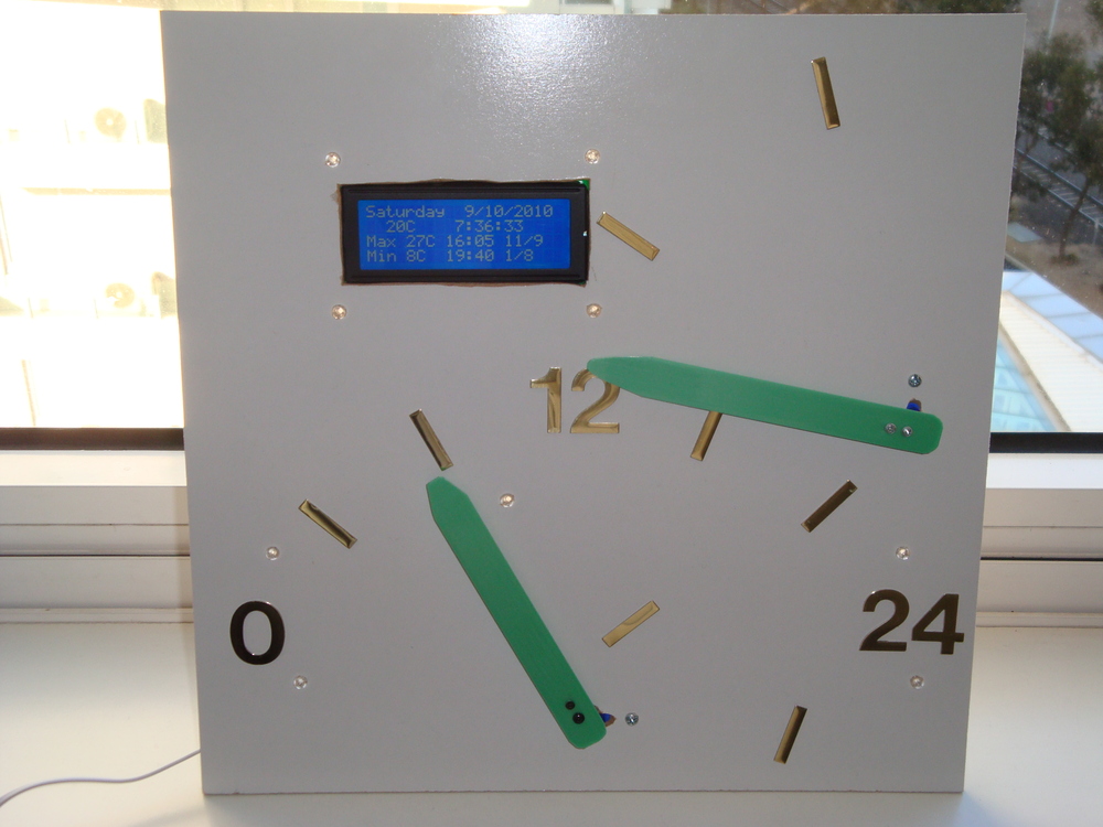
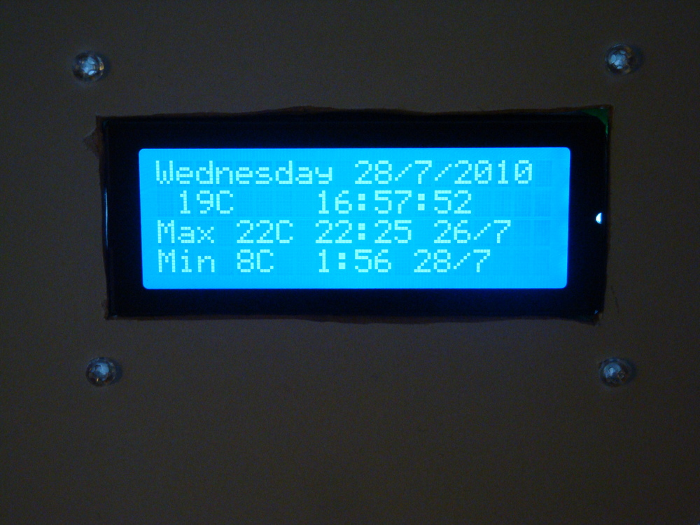
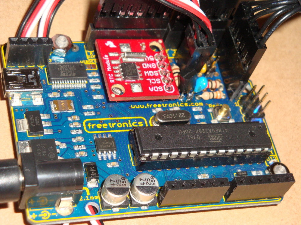
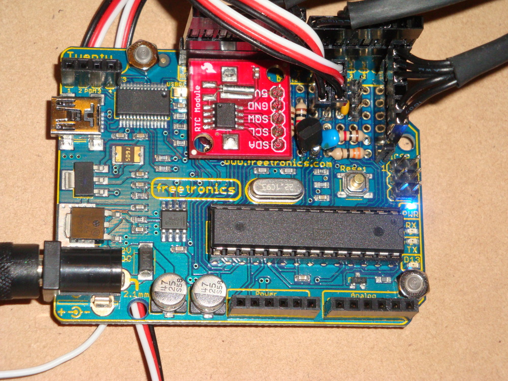
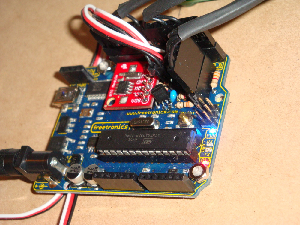
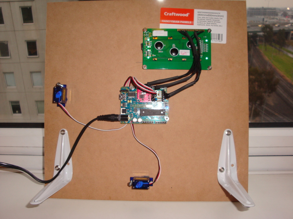
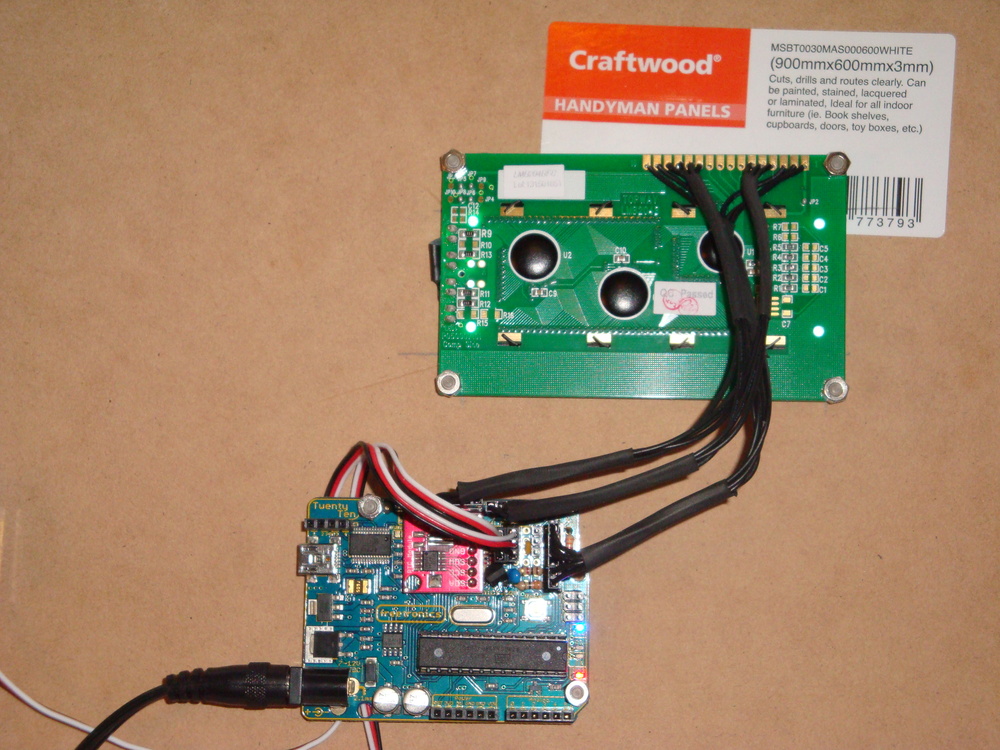
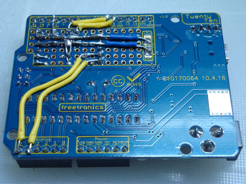
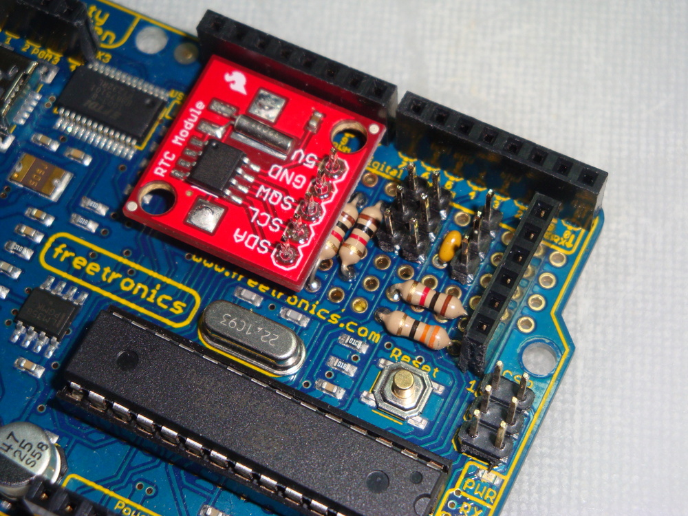
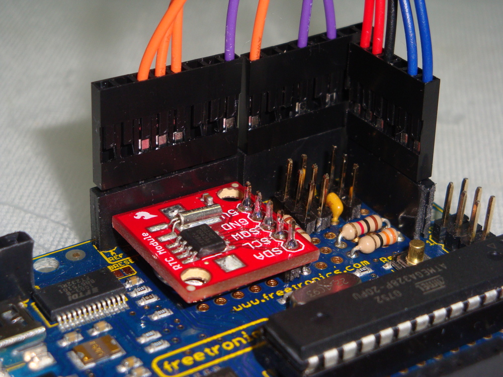
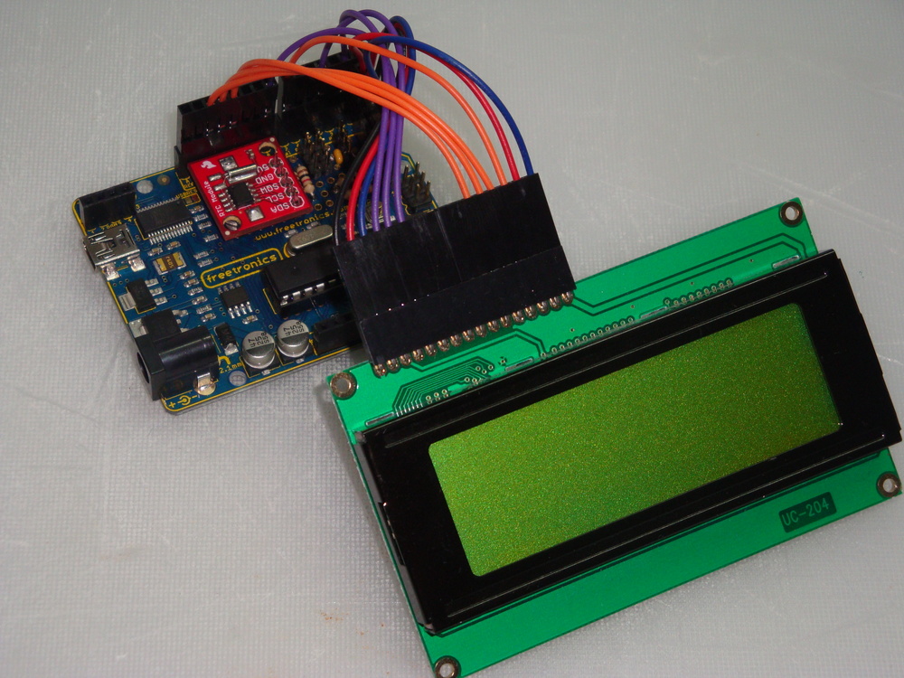
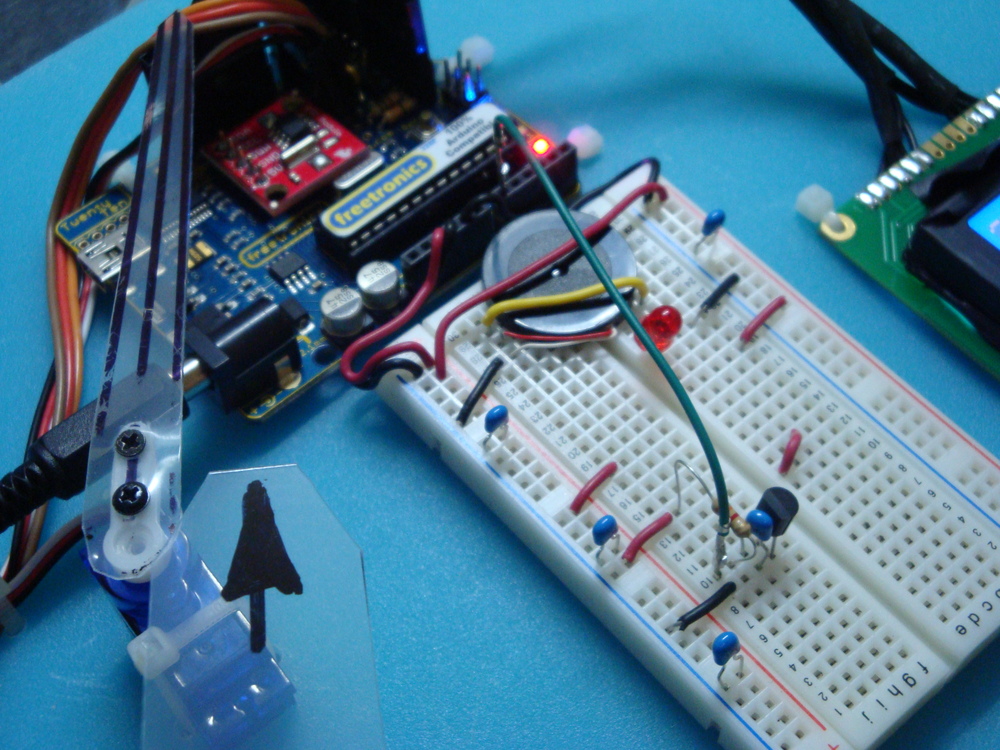
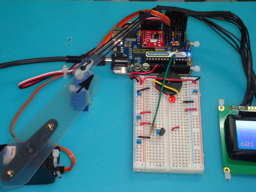
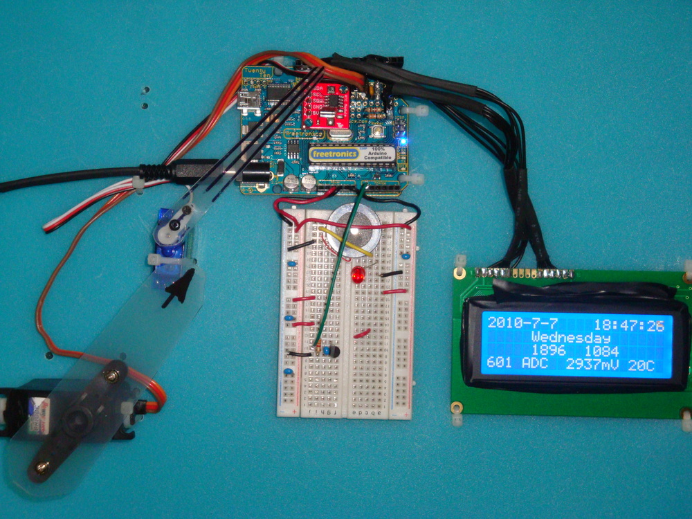
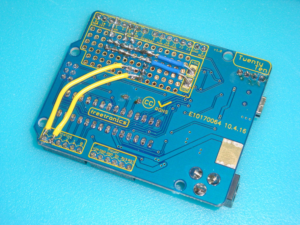
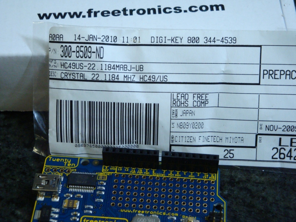
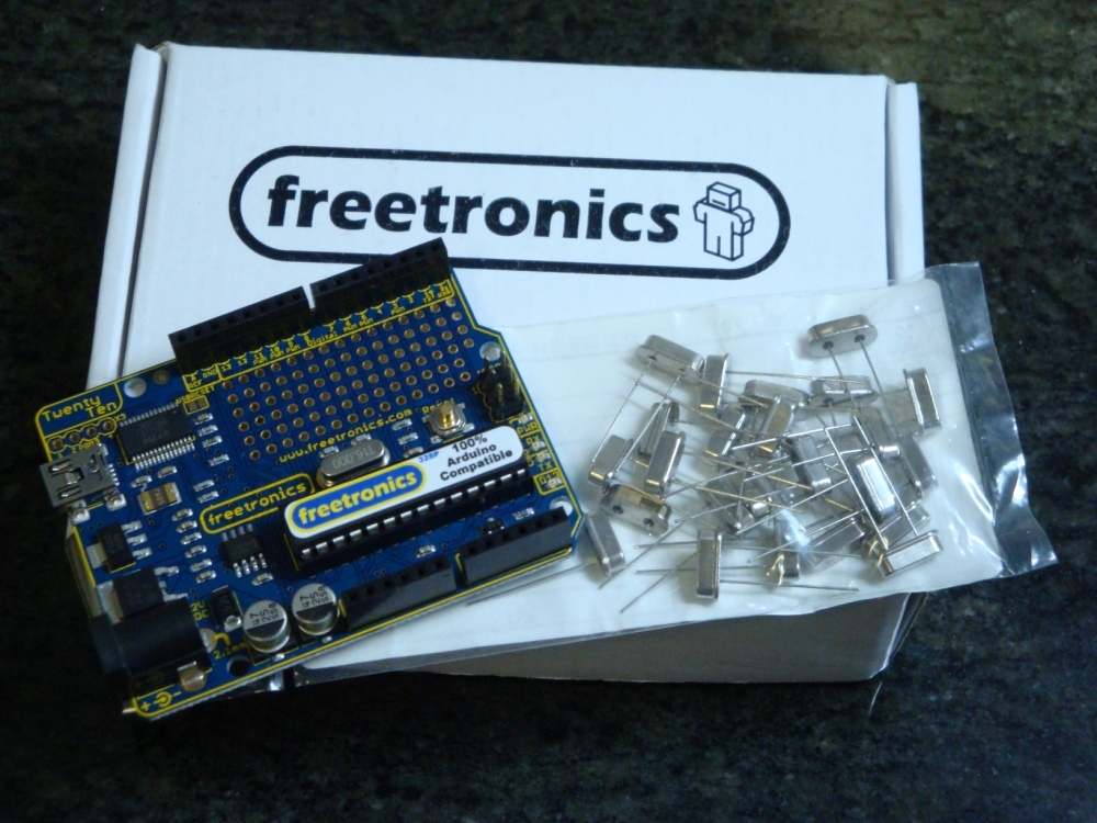
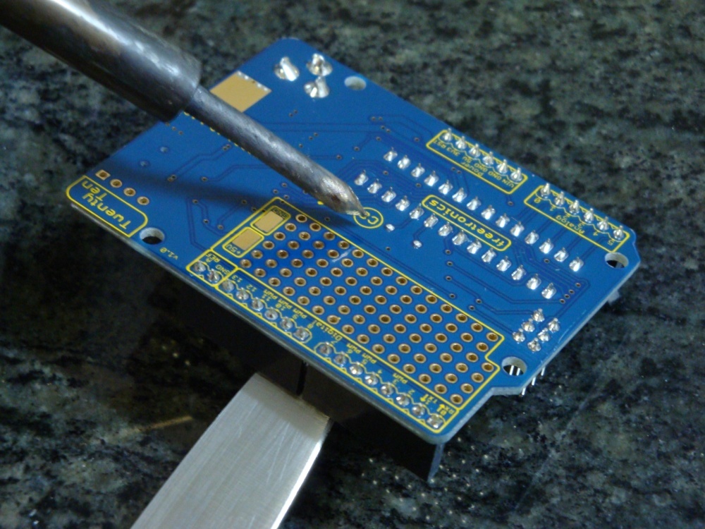
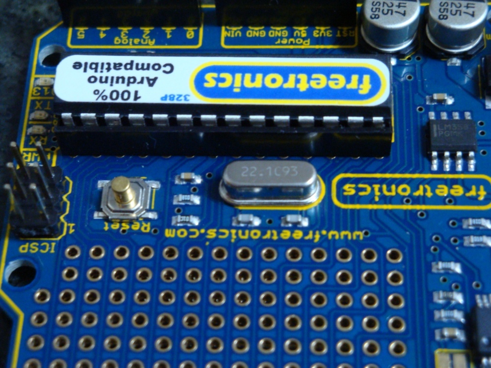
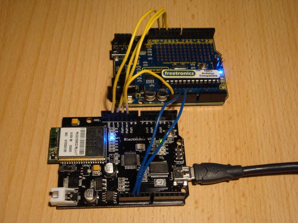
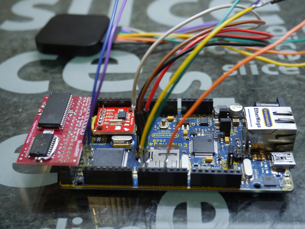
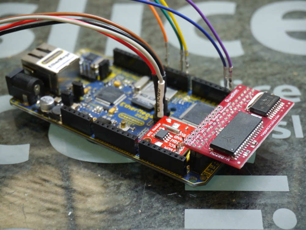
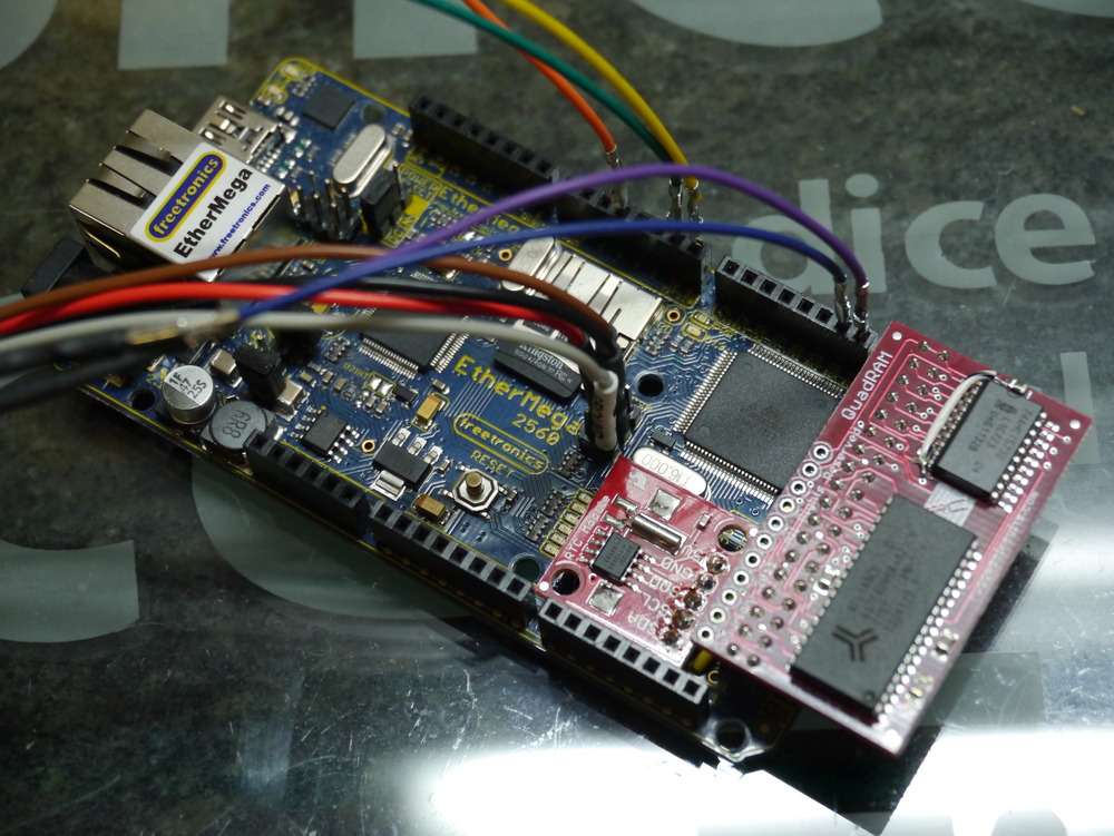
Here are some pictures.

P1010781P1010782P1010783

And here are the links to the products described.

Rugged Circuits QuadRAM


I’m very happy with my Saleae Logic too. Must write a review on this, one day. Great tool, more useful every day.

The described code is all available on Sourceforge, if you’re intending to try this at home.

The only finished example using the memory routines is the MegaSD project. Take a look at it on Sourceforge to see how to use the extra RAM.

HOW TO

What do we have to do to get this build working? Well it is pretty simple really, once everything is figured out. It is really only three steps.

  1. Initialise the RAM, and tell the AVR that it should enable its extended RAM bus.
  2. Tell the compiler that you’re moving the heap into the new extended RAM address space.
  3. Tell freeRTOS to move its heap to the new extended RAM address space.

Initialise the RAM

The RAM should be initialised prior to building the standard C environment that comes along for the ride. It can be done in the .init1 (using assembler) or in .init3 in C. I built both methods, but elected to just use the C method, as it is more maintainable (legible).

There are a number of references for this code. Some of the older ones refer incorrectly to a MCUCR register. That is not correct for the ATmega2560.

This example covers what Rugged Circuits suggest for their testing of the QuadRAM, but it doesn’t put the initialisation into .init3, which is needed to make the initialisation before heap is assigned. It makes the initialisation carefree.

// put this C code into .init3 (assembler could go into .init1)
void extRAMinit (void) __attribute__ ((used, naked, section (".init3")));
void extRAMinit (void)
{
// Bits PL7, PL6, PL5 select the bank
// We're assuming with this initialisation we want to have 8 banks of 56kByte (+ 8kByte inbuilt unbanked)
DDRL  |= 0xE0;
PORTL &= ~0xE0;  // Select bank 0
// PD7 is RAM chip enable, active low. Enable it now.
DDRD |= _BV(PD7);
PORTD &= ~_BV(PD7);
// Enable XMEM interface
XMCRA = _BV(SRE); // Set the SRE bit, to enable the interface
XMCRB = 0x00;

To ensure that this .init3 function, that I’ve put into lib_ext_ram, is included in your linked code, we need to call something from the lib_ext_ram library. If you’re planning to use the banks of RAM, then this is easy as you’ll naturally be calling the bank switching functions.

However, if you only want to use the extra 56kByte of RAM for simplicity (it is after all 7x more than you have available with just the internal RAM), then just call this function once from somewhere, possibly main(). I have added it to the freeRTOS stack initialisation function in port.c, so I don’t need to see it ever again.

extRAMcheck();

It returns the XMCRA value, that can be tested if you desire. But there’s no need as things will anyway have gone badly pear shaped if the RAM is not properly enabled. Calling this once is all that is needed to ensure that the .init3 code is properly inserted into the linked code.

Note: that the above code is specific to the QuadRAM device. The MegaRAM device has different IO in use, and the differences are noted in my code on Sourceforge.

Move the heap

The standard C heap has to be moved to the new location above the stack. There are other memory allocation options, but in my opinion this is the most sensible one and the only one I’m planning to implement.

The __heap_start and __heap_end symbols describe the addresses occupied by the extended RAM, and inform malloc() of the location of the heap. This is described in more detail here http://www.nongnu.org/avr-libc/user-manual/malloc.html. This is a great diagram showing the situation.

Malloc-x2
avr-gcc -Wl,-Map,MegaSDTest.map -Wl,--gc-sections -Wl,--section-start=.ext_ram_heap=0x802200  -Wl,--defsym=__heap_start=0x802200,--defsym=__heap_end=0x80ffff -mmcu=atmega2560 -o "MegaSDTest.elf" $(OBJS) $(USER_OBJS) $(LIBS)

Tell freeRTOS

Now freeRTOS has to be made aware of these changes to the heap location. There are three heap management options available for the AVR port. The two most memory economical options use a fixed array of memory defined in the .data section on initialisation. Clearly, this is not going to be useful. For the third option heap_3.c, which uses malloc(), we have nothing more to do.

However, getting heap_1.c and/or heap_2.c to work is not that complicated either. There are three parts to this. Firstly, creating a new section name, and locating it at the start of the desired heap space. We’ve already done that, above, with the –section-start command. The forth option heap_4.c has also been implemented.

Secondly, we have to make a small modification to both heap_1.c heap_2.c and heap_4.c to inform the compiler that the freeRTOS heap will be located at this .ext_ram_heap location. That is done in this manner (heap_2.c shown).

static union xRTOS_HEAP
{
//... edited ...
unsigned char ucHeap[ configTOTAL_HEAP_SIZE ];
//... edited ...
#if defined(portEXT_RAM)
} xHeap  __attribute__((section(".ext_ram_heap"))); // Added this section to get heap to go to the ext memory.
#else
} xHeap;
#endif

And finally, now we’ve (probably, just because we can) allocated a large (up to 32kByte maximum) freeRTOS heap, we need to ensure that the loader omits this section from its preparations for writing the .hex file to flash (in a similar manner to the way the .eeprom section is removed).

avr-objcopy --remove-section=.eeprom --remove-section=.ext_ram_heap -O ihex MegaSDTest.elf  "MegaSDTest.hex"

Something to watch for is that none of your other code is calling malloc(), because if it does its memory allocations will collide with the freeRTOS heap. Either check that malloc() is not being linked in or, for the paranoid, just assign the heap_1.c heap_2.c or heap_4.c heap to a region separate to your new malloc() heap addresses.

And that’s all there is to getting an easy 512kByte of fast no-wait-state RAM on your Freetronics EtherMega or Arduino Mega2560. Enjoy!

Freetronics freeRTOS Retrograde Real Time Clock (DS1307) – Part 3 Final

In Part 2  I promised to build a very stylish finished product, that could be displayed with pride. Well, I don’t think I’ve quite achieved that. But, at least now I consider the project finished, and now have the confidence to get on with other projects.

I have mounted some tiny servos, the funky white on blue LCD display, and the Freetronics 2010 board on some Craftwood. Cutting the hole for the LCD was a bit hit & miss, using a carving knife to shape the hole, and managing not to loose any fingers in the process.

Dsc04060Dsc02851

The hour servo is mounted at the bottom of the board, and travels clockwise from midnight, with noon vertical, until it re-tours to 0 on the stroke of midnight. The hour hand travels clockwise from 0 minutes at the bottom, over 30 minutes horizontal, to 59 minutes at the top of the stroke. At 0 minutes, the minute hand re-tours to 0 at the bottom. I find the movement of the servos on the stroke of the hour somewhat like a chime. Not too oppressive, but enough to draw my attention to the passing of another hour.

As the 4 line LCD has so much screen real estate, I have added the maximum and minimum temperature display, with hour, day and month when each extreme was reached.

Adding the LM335Z Temperature IC was discussed in Part 2. I found that the accuracy of the LM335Z IC could be improved by firstly knowing exactly what the Vcc was for operating the AVR device. Measuring this, and putting it in the calculation enabled enough accuracy to be found. Using the 5V regulator on the Freetronics 2010 delivered 4.97V for me, and this value is hard coded into the code. I have several LM335Z devices and they have different offsets, which is adjusted by modifying the subtraction in the Kelvin to Celsius calculation. As the LM335Z is accurate once the offset is established, there is no need to operate it in the “accurate” mode, IMHO, given we have software to make the adjustments it needs.

Dsc02855Dsc02852Dsc02854

The instability in the temperature readings discussed in Part 2 was caused by the long wires to the sensor. Once the device was fixed into the prototyping area on the 2010, together with bypass capacitor, the stability of readings improved greatly. However, during testing, I noted that the maximum values were reading very high. These false high maximum values were caused because the ADC process was sampling during a servo move. The servos consume a lot of power, and this causes voltage drop on Vcc. Hence the reference voltage for the ADC is no longer accurate.

Dsc02845Dsc02847

To prevent the ADC from operating during the servo moves, I simply used one of the freeRTOS semaphores I established previously. I use semaphores to control access to the LCD, the I2C and to the ADC. Use of a semaphore enables independent processes to share a single hardware resource without conflicts developing. The fix for the erroneous high maximums was done simply by taking the ADC semaphore (to prevent the ADC reading process from starting) during times when the servos are being instructed to move. Simple, with freeRTOS to manage the process interaction for me.

ERRATA

The code included in the updated source does not properly fix the issue of false maximum temperatures. It incorrectly releases the ADC semaphore immediately following resetting the PWM values. This means that the hands can still be moving when the ADC process gets unblocked which causes false maximums, because of voltage droop in Vcc, typically at midnight when both hands are in motion.

The fix is to move the vTaskDelay call between the set_PWM_hardware and xSemaphoreGive calls. I also increased it to 2000 milli Seconds too, to ensure the hands are really stopped before the ADC process gets unblocked.

set_PWM_hardware( servoHours_uS, servoMinutes_uS );

vTaskDelay( 2000 / portTICK_RATE_MS ); // a 2 second delay to ensure the hands have properly stopped.

xSemaphoreGive( xADCSemaphore );


END ERRATA

Another piece of code added since Part 2 is to write the maximum and minimum temperatures and the times the extremes occurred into the EEPROM available on the 2010. The functions to use the EEPROM are available in the AVR library and are very straightforward to use. Having a permanent record of temperature extremes is perhaps one thing this clock does, that other clocks in my house can’t do.

There are a lot of comments in the updated freeRTOS Retrograde Clock code, now hosted at Practical Arduino. As a reminder the code uses the AVR and Pololu Libraries, so these both need to be installed before you compile.


Freetronics freeRTOS Retrograde Real Time Clock on PS3 – Part 2a

Just for interest, I decided to see how the support for AVR or Arduino was on the PS3.

Using the standard tools on Ubuntu Lucid 10.4 from my OtherOS installation. A quick search for AVR on synaptic got the avr-lib, avr-gcc, and avrdude tools needed. No special versions, just straight off the repository.

Then, I followed the link to the Pololu Libraries in my Part 2 post, made the changes to OrangutanLCD.h as noted, hit make, and crossed my fingers. No issue. It all worked. sudo make install to put the files in right place.

OK. does the PS3 USB platform recognise the FTDI 232RL USB chip on the Freetronics 2010? Yes. Another hurdle cleared, with no issues.

With that step done, it was simple to download the retrograde files from Practical Arduino as noted in Post 2, extract them. Hit make program and off we go. avrdude works as expected, and the new code is loaded as normal.

I’d say the whole test was over faster than it has taken to type this note.

I should be over this, but I get so happy when technology just works… particularly when it is all free. Got to love your FOSS.

One small issue. There doesn’t seem to be a release of Arduino tools for PS3 (PowerPC). Pity about that. Perhaps in another repository…

Freetronics freeRTOS Retrograde Real Time Clock (DS1307) – Part 2

Part 2 of this project involved learning how to use hardware PWM to control servos. And, then to make the clock actually work with retrograde analogue hands.

First the functional definition. A retrograde movement in horological terms is where the indicators or hands spring back to their home or 0 position at the end of their cycle. So for a minute hand, after 59 minutes and 59 seconds, its next movement would be to reverse move to home at 0 minutes. For the hour hand this could happen after 12 hours or 24 hours. 24 hours is the case that I have chosen to implement. The idea is to have the hour hand trace out a day from sunrise in the east, to vertical noon, and to set in the west.

In part 1, I added the servo headers to align with the Arduino Digital Pins 5 & 6. These pins are driven by the Timer 0 PWM hardware. Following quite a few evenings trying to understand how to generate PWM using the hardware (OK, I’m a bit slow), I realised that it is not very easy to get a good servo signal out of Timer 0 or Timer 2.

To generate the right signal for a servo, you need to produce a pulse every 20mS (50Hz). The width of the pulse should be 1.5mS to get the neutral position. Depending on the servo design, pulses with width from around 0.8mS to around 2.2mS (repeated every 20mS) will drive it to either end of its range. Depending on the servo, 0.8mS may drive it clockwise or anticlockwise. I have both in the clock. For example, the “hour” servo goes clockwise with a wider pulse. The “minute” servo is the reverse case.

The main issue with Timer 0 and Timer 2 is that they are 8 bit timers, counting to 255 before resetting to 0 (ideally after 20mS). Since the required pulses are between 0.8mS and 2.2mS, there are only about 12 “positions” available for the servo to take. Not enough to allow a minute hand to indicate 60 different positions.

Therefore it became clear that, for this application, it was only possible to use the 16 bit Timer 1 to control the servos.

Setting up Timer 1 is relatively easy, once that decision had been made, so the code was implemented. But, this meant that I had to reconnect the servo headers to Arduino Digital Pin 9 and Pin 10, which are driven by the Timer 1 PWM hardware.

Also, in the pictures below, I have added a header to allow power, LCD backlight (32Ohm), and contrast (1kOhm), connections to the standardised HD44780 LCD.

Dsc02787Dsc02791Dsc02789

Ok, so here’s the issue. I’m using the Pololu Libraries for writing to the LCD, and the standard connection for the data line 4 on the HD44780 LCD goes to Arduino Pin 9. The same pin I need for the Timer 1 PWM. Ouch.

Modifying the library is not too difficult. We can move the Data line attached to Pin 9 onto Pin 11, and all is well. This is done in the following file.

~/libpololu-avr/src/OrangutanLCD/OrangutanLCD.h

The changes are noted in the #define lines below

#define LCD_DB4                PORTB3        // Was PORTB1. Use PORTB3 to avoid the Timer1 pins.
#define LCD_DB5                PORTB4        // PB4
#define LCD_DB6                PORTB5        // PB5
#define LCD_DB7                PORTD7        // PD7

//    PortB:     7 6 5 4 3 2 1 0
//  LCD Data:      2 1 0            Use DB3 to avoid Timer1 pins.
//  LCD Data:      2 1     0
//
//  PortD:     7 6 5 4 3 2 1 0
//  LCD Data:  3

#define LCD_PORTB_MASK            ((1 << LCD_DB4) | (1 << LCD_DB5) | (1 << LCD_DB6))  // Modified to avoid using DB1
#define LCD_PORTD_MASK            (1 << LCD_DB7)
#define LCD_PORTB_DATA(data)    ((data & 0x07) << 3)  // Modified the data mask to avoid using DB1
#define LCD_PORTD_DATA(data)    ((data & 0x08) << 4)

The below pictures show the LCD pin layout.
<blockquote”>Red = VCC

Black = GND

BLUE = Voltage for contrast or backlight

Orange = Data lines (4-bit: DB4 – DB7) PB3 (not PB1), PB4, PB5, and PD7. Arduino Digital pins 11 (not 9), 12, 13, and 7

Purple = Control lines (RS, R/W, E) PD2, PB0, and PD4. Arduino Digital pins 2, 8, and 4

Dsc02793Dsc02796

So now we have PWM for our retrograde analogue hands, and a LCD display.

But wait, there’s more…

There’s too much display going to waste, so let’s add something else… Hmm… Temperature, and time, make a min/max thermometer that can show what time each extreme temperature was reached during the day.

Quickly getting a LM335Z temperature sensor, I’m now testing whether the 10bit ADC is good enough to generate reasonable temperature readings from the device. At full range of 5000mV across 1024 levels, we have about 4.88mV per level. The LM355Z produces 10mV per degree, so we should be able to get 0.5 degree accuracy. If everything is perfect.

Currently the temperature gauge works, but the accuracy is still a work in progress, as are the min / max functions. The LM335Z has only two connections, and is biased by a single resistor (3200 Ohm), so it will fit into the board if that is all that is needed. Getting perfection may require addition of decoupling capacitors on AREF and across the sensor, but I’m still
experimenting with this.

Dsc02838Dsc02839

The overall working product is shown below. But wait, there’s more…

I was not happy with using resistors to tie up the SCL and SDA lines high for the I2C bus, as it should be possible to use the internal pull up resistors in some situations (according to the Atmel datasheet).

So using a new Freetronics 2010 from Little Bird Electronics, the clock is now rebuilt without external pull up resistors. The I2C code is modified to only pull up the lines between the start and stop bus instructions. The levels are messy (not showing sharp transitions in my SLO) but, never the less the code and the clock works.

The working device is shown below. Note the rather funky white on blue display I got from Sparkfun.

Dsc02842

In the years since this instruction was writen, I’ve migrated to Github. So the code is hosted here. The freeRTOS code is also posted on Github. I used the Pololu Library for writing to the display, so it needs to be installed along with the normal AVR libraries.

Part 3 will look at how to build a really stylish clock face that can be shown off in public

Freetronics 2010 (Arduino Duemilanova) freeRTOS Real Time Clock (DS1307) – Part 1

I was pondering the blank space on my 2010 recently, and combining that space with some other left over kit from Dogbot, I decided to make a dual retrograde analogue clock.

To build the clock I have the choice of either using NTP to sync a wireless enabled device, or use a RTC clock and re-set it every month or so. For this iteration, I’ve decided to go the RTC route.

Actually, reading this Tronixstuff page also got me going on the idea of using a DS1307 chip, and also Sparkfun makes a nice module that just happens to fit in the vacant space on the 2010. So, I bought one from LittleBird Electronics.

Only other thing to do was to add some servo headers, to get me going with the analogue clock face (using servos).

The picture below shows the layout. I tried a few different options, but this layout seems to only affect the legibility of the pin labelling. Other layouts mask the crystals close together, and I’m not sure how that would affect clock accuracy, or prevent the battery from being removed (9 years later).

Dsc02777

Yes, everything fits. Now to the soldering iron.

Dsc02779

Ok now it is soldered together, and everything looks reasonably fine.

Dsc02780Dsc02781

Now, on the test bed, I have the RTC clock working well using my beloved freeRTOS, and can get on with using the servos to drive analogue hands.

Dsc02785Dsc02784

In the years since this instruction was writen, I’ve migrated to Github. So the code is hosted here. The freeRTOS code is also posted on Github. I used the Pololu Library for writing to the display, so it needs to be installed along with the normal AVR libraries.

Part 2 looks at building the PWM control for the retrograde hands, and adding a temperature function.

Freetronics 2010 (Arduino Duemilanova) Overclocking & Review

Recently, I picked up a Freetronics 2010 from Little Bird Electronics.

Dsc02744

I thought that it would make a nice upgrade to my Dogbot test bed. It uses the same USB connector as Dogbot’s Pololu SVP, so it saves me from keeping different USB cables handy, but is in every way 100% the same as the Arduino Duemilanove that I’ve been using up to now.

But, everything I own is hacked in some way. So as usual, I thought that the 2010 could be improved, just as I’ve improved the Duemilanove before it, by overclocking it to 22.1184MHz.

Overclocking to 22.1184MHz

So why change the clock frequency to this odd number of 22.1184MHZ, and not to 20MHz which would be in specification?

It turns out that because of the binary and integer world the 2010 and the Duemilanova ATmega328p MCU live in, it is much better have a “nice” binary and integer friendly base frequency. Unfortunately, although 16MHz on a 2010 or Arduino sounds nice, from the point of view of integer programming, clock scaling, and UART interfacing, it is difficult to get clean integer numbers.

A small example.
16MHz clock scaled to 115200baud = 138.888888889 so rounding gives an error term.
20MHz clock scaled to 115200baud = 173.6111111111 so, again, rounding gives an error term.
22.1184MHz clock scaled to 115200baud = 192 with no rounding error.

Also, even though we are getting 16,000,000 instructions per second out of a standard?2010, and that should be enough for any application. I can get 22,118,400 or a 38% improvement for the cost of a few cents. So, why wouldn’t you?

What kind of issues can occur?

Well, over-clocking means that the ATmega328p is out of specification. But, I’m not too worried about pushing specification on this project, as the 328p is certified for an industrial operating temperature range, which is way outside of my operating temperature… There are also unverified reports of AVR ATmegas working successfully up to 32MHz.

In the overall scheme of things, raising the clock frequency on the AVR ATmega328p above specification by 10% to 22.1184MHz is no big deal.

Upgrading Process

1. Obtain a 22.1184MHz HC49/US crystal from Digikey They’re pretty cheap. Buy a bag in case of accidents.

Dsc02746Dsc02747

2. Use a knife tip under the existing 16MHz crystal to give you a lever to pressure it into removal, without burning your fingers. It will get very hot!

3. Turn over the board and use a soldering iron to heat the joints, whilst leaning on the knife to lever out the 16MHz crystal. Once it is removed, use some solder wick or similar to remove excess solder, and make it easier to insert and solder the new 22.1184MHz crystal.

Dsc02751Dsc02750Dsc02755

4. Building a new bootloader. In replacing the crystal, the 2010 is effectively bricked. You can no longer communicate with it using the standard bootloader. It is now running too fast and out of specification for avrdude to communicate with it, so we have to compile and burn a new boot loader before we go any further. I choose to use the Adaboot328 bootloader from Ladyada. It resolves a few known issues with Arduino compatible boards, and is easy to compile.

In the ATmegaBOOT_xx8.c file, change the UART baud rate to 115200, if you use avrdude for programming (if using Arduino IDE, do not change this from 19200). Who has time to wait around these days for 19200 baud, anyway?

/* set the UART baud rate */
#define BAUD_RATE?? 115200

In the Makefile, change the AVR_FREQ value to 22118400L for the adaboot328: TARGET.

adaboot328: TARGET = adaboot328
# Change clock frequency from 16000000L
adaboot328: AVR_FREQ = 22118400L

Then, compile the bootloader, and keep it safe.

5. Prepare an ISP. There are many alternative ways to do this, and here is not the place to describe the alternatives. Suffice to say that I used the AVRISP method in the Arduino-0018 IDE. I’ve struggled with avrdude (which I otherwise use for everything) as a bootloader ISP. I don’t know why, but I can’t make it work.

It happens that I have a standard Arduino clone available, which I prepare as the AVRISP, by uploading the following sketch File>Examples>ArduinoISP.

6. To be able to use Arduino IDE to burn our special bootloader, you have to replace the standard ATmegaBOOT_168_atmega328.hex bootloader file, found in ~arduino/bootloaders/atmega/ with our newly generated file. And, to make things simple, I just rename or remove the standard one, and replace it with our newly prepared and renamed bootloader with this name
ATmegaBOOT_168_atmega328.hex.

7. Connect our Freetronics 2010 up using the AVRISP connections, described on the Arduino web site. Make sure we have the right board type selected; it should be Duemilanova w/ ATmega328. Then using the Arduino IDE use Tools > Burn Bootloader > w/ Arduino as ISP.

Dsc02756

8. Program a sketch using either the Arduino IDE, or using avrdude, remembering that the baudrate is set to 115200. And, enjoy.

Conclusions regarding the Freetronics 2010.

Its a very well designed and produced device, that is 100% compatible with the Arduino Duemilanova. Some advantages are: the mounting holes are slightly larger so cable ties go through nicely, smaller USB connector is more common than the B connector used on Duemilanova, and there’s no solder in the holes for the X3 connector so it is easy to add headers to make it possible to burn its own bootloader (if you want).

It runs my freeRTOS build with no problems, as seen in this demo on my Dogbot test bed with a Robot Electronics Thermopile, and Sharp IR Distance sensor.

Dsc02760Dsc02761

DogBot – Post 5

So some time has passed and I’ve had some success with different aspects of my robot.

For simplicity, I’m using a test bed based on an Arduino Duemilianova connected to a Nerdkits sourced display. I’ve hooked the display up as if it was a Pololu Orangutan SV-328 and am using Pololu libraries to write to it. Also, I’ve been working on the actual SVP based robot, so both of which are working well.

The processor 328p is used for the Duemilianova and requires the use of the Timer0, which implies no Pololu motor library code is possible without conflicts. However this is not an issue, as the Duemilianova doesn’t have motor drives anyway. The actual DogBot has the 1284p which is used in the SVP and uses Timer3, which has no limitations on any known libraries to my knowledge.

The freeRTOS code is posted on the Pololu Forum, mostly just back-up as the application code is very immature.

At  this stage I’ve got all of the I2C bus based sensors working, based on code developed by Fleury. So, I can read the thermal sensor for its 8 pixels, and equally importantly, I can read the SRT10 Ultrasonic Sensor for distance in cm. One issue with the ultrasonic sensor is that its field of vision is so great that it basically detects anything “in front” of it. Good to not run into things, but pretty useless as a fine directional capability. It seems lucky that the Sharp IR distance sensors are very directional, and sufficiently accurate as a complement. The analog sensor readings are working well too, though I still have to create a ADC to cm regression.

From the point of view of sensing, it looks like the Sharp IR sensors will be the reference. With the SRT10 sonar being most relevant to create a “zone of safety” where I can be assured that the nearest object in a cone of 120deg is measured, but can’t be sure exactly which direction the object is. On the thermal side, I will get a vector (direction and temperature) from the sensing location, but no distance. But, that I knew and expected.

Putting some effort into designing the motor control, or Transport Task, has taken up my thoughts recently. I don’t want to link the odometry available from the quadrature encoders back into the mapping or routing task. Similarly, I don’t want to link the intertial navigation available from yaw and linear acceleration sensors into the motor task.

I think the transport task should simply take a vector,  relative to the the current pose of the robot, and execute these translation commands subject to feedback from odometry, leaving the inertial navigation to another task.

This fits well into the design of the hardware, as odometry can can be queried from the Pololu SVP ancillary processor, without blocking, and the motor PWM drivers can be also managed without blocking other tasks. This creates a self contained task that does not need to share resources with other tasks.

However, the inertial sensors are analogue readings and the ADC will need to be shared with the Sharp IR distances sensors. Creating the need for a semaphore, and blocking based on the availability of the ADC.

Because of the battery issues described in Post 4, I’ve had to remove the servo neck of the DogBot. Therefore, I will implement the option for motion to be along circular paths, as well as along a straight line. Motion along a straight line, with stationary rotations to create the correct pose prior to departure, are the best paths to arrive at the destination with the lowest risk and shortest path. However, with a fixed sensor head, straight lines don’t fill the map with information as they leave the sensors always pointing in the same direction.

If the DogBot proceeds from A to B via a circular route (if this is requested by the mapping or logistics task), then the sensors will be pointed at all directions from +90 to -90 degrees along the path to the destination. Allowing the travel time to be used effectively for data acquisition.

If I’m feeling smart, then I can create any number of route subdivisions, and force DogBot to describe a path of smooth semicircles to the destination, gathering sensor data along the route.

The inertial sensors can be run in a parallel task (using the ADC along with the Sharp IR sensors), with the odometry (from the ancillary processor) to cross check that the expected distances and directions are traveled. Whilst I think the odometry is more likely to be accurate, the map will be updated constantly so some inaccuracy should be expected and tolerated by the code.

My next step is to design this transport task. This task should take distance, bearing and path description (straight line, circle, sinusoidal, etc) and carry it out to the best of its ability (odometry PID data only). I expect resolving this effort will take the next few weeks, and perhaps longer.

Later work is to develop the logistics and routing task that will issue the navigation requests to the transport task.

Continued with Post 6 (one year later).

Wifi Dogbot – Post 3 – Pin Outs

Changed the processor to Pololu Orangutan SVP

*** PIN OUTS DEFINED

For the Orangutan SVP from http://www.pololu.com

Port Pin Orangutan (Alternate Functions) Function Notes

  • PA0 (ADC0) IR Analogue Distance Sensor GP2Y0A02YK0F (20cm-150cm) to ~2.8V – ORANGE
  • PA1 (ADC1) IR Analogue Distance Sensor GP2Y0A21YK0F (10-80cm) to ~2.8V – WHITE
  • PA2 (ADC2) LISY GIRO Z Axis Analogue Sensor to 3.3V – PURPLE
  • PA3 (ADC3) MMA7260QT Three Axis Accelerometer – X Axis Analogue to 3.3V – YELLOW
  • PA4 (ADC4) MMA7260QT Three Axis Accelerometer – Y Axis Analogue to 3.3V – BROWN
  • PA5 (ADC5) MMA7260QT Three Axis Accelerometer – Z Axis Analogue to 3.3V – GREEN
  • PA6 (ADC6) Motor1 Current sense – WHITE
  • PA7 (ADC7) Motor2 Current sense – WHITE
  • PB0 (T0) LCD control line RS Timer/Counter 0
  • PB1 (T1, CLKO) LCD control line R/W
  • PB2 (AIN0, INT2) LCD control line E
  • PB3 (AIN1, OC0A) Timer0 PWM output A? PIR (Digital LOW) – YELLOW (& RED & GREY)
  • PB4 (SPI_SS, OC0B *) Timer0 PWM output B
  • PB5 (SPI_MOSI) auxiliary processor control
  • PB6 (SPI_MISO) auxiliary processor control
  • PB7 (SPI_SCK)? auxiliary processor control
  • PC0 (I2C_SCL) Ultrasonic Ranger SRF10 Addr 0xE0 & Thermopile Addr 0xD2 – BROWN
  • PC1 (I2C_SDA) Ultrasonic Ranger SRF10 Addr 0xE0 & Thermopile Addr 0xD2 – ORANGE
  • PC2 LCD data line DB4 – user pushbutton (pressing pulls low)
  • PC3 LCD data line DB5 – user pushbutton (pressing pulls low)
  • PC4 LCD data line DB6 – green user LED (high turns LED on)
  • PC5 LCD data line DB7 – user pushbutton (pressing pulls low)
  • PC6 Motor2 direction control line – LEFT MOTOR
  • PC7 Motor1 direction control line – RIGHT MOTOR
  • PD0 (USART0_RXD0)
  • PD1 (USART0_TXD0) digital I/O red user LED (low turns LED on)
  • PD2 (USART1_RXD1, INT0)
  • PD3 (USART1_TXD1, INT1)
  • PD4 (OC1B) Timer1 PWM output B – Buzzer
  • PD5 (OC1A) Timer1 PWM output A – I/O servo SPWM? – Neck Servo
  • PD6 (OC2B) Timer2 PWM output B – Motor2 speed control line
  • PD7 (OC2A) Timer2 PWM output A – Motor1 speed control line
  • AREF VCC 3.3V Battery Supply

IN PHYSICAL ORDER

TOP RIGHT TO LEFT

  • PD5 (OC1A) Timer1 PWM output A – I/O servo SPWM – Neck Servo
  • Quadrature Sensor D – YELLOW (LEFT 2nd)
  • Quadrature Sensor C – WHITE (LEFT 1st)
  • Quadrature Sensor B – BLUE (RIGHT 2nd)
  • Quadrature Sensor A – BROWN (RIGHT 1st)
  • GND

BOTTOM RIGHT TO LEFT

  • VIN
  • GND
  • M1 OUT B – PURPLE (RIGHT)
  • M1 OUT A – GREY (RIGHT)
  • M2 OUT B – ORANGE (LEFT)
  • M2 OUT A – GREEN (LEFT)=
  • PD3 (USART1_TXD1, INT1)
  • PD2 (USART1_RXD1, INT0)
  • PD1 (USART0_TXD0) digital I/O red user LED (low turns LED on) blank
  • PD0 (USART0_RXD0) blank – reserved
  • PC1 (I2C_SDA) Ultrasonic Ranger SRF10 Addr 0xE0 & Thermopile Addr 0xD2 – ORANGE
  • PC0 (I2C_SCL) Ultrasonic Ranger SRF10 Addr 0xE0 & Thermopile Addr 0xD2 – BROWN
  • PB4 (SPI_SS, OC0B *) Timer0 PWM output B
  • PB3 (AIN1, OC0A)???? Timer0 PWM output A PIR (Digital LOW) – YELLOW (& RED & GREY)
  • PA0 (ADC0) IR Analogue Distance Sensor GP2Y0A02YK0F (20cm-150cm) to ~2.8V – ORANGE
  • PA1 (ADC1) IR Analogue Distance Sensor GP2Y0A21YK0F (10-80cm) to ~2.8V – WHITE
  • PA2 (ADC2) LISY GIRO Z Axis Analogue Sensor to 3.3V – PURPLE
  • PA3 (ADC3) MMA7260QT Three Axis Accelerometer – X Axis Analogue Sensor to 3.3V – YELLOW
  • PA4 (ADC4) MMA7260QT Three Axis Accelerometer – Y Axis Analogue Sensor to 3.3V – BROWN
  • PA5 (ADC5) MMA7260QT Three Axis Accelerometer – Z Axis Analogue Sensor to 3.3V – GREEN
  • PA6 (ADC6) Motor1 Current sense – WHITE – RIGHT MOTOR
  • PA7 (ADC7) Motor2 Current sense – WHITE – LEFT MOTOR
  • AREF VCC 3.3V Battery Supply (to centre board) – BLUE

Wifi Dogbot – Post 2

Construction NOTES

   1. Build chassis platform for use indoors.

Chassis platfrom elements come from Pololu, so it will be good to use their Orangutan libararies wherever possible. I will need to modify them as the Arduino/Blackwidow runs at 16MHz (not at 20MHz).

Should I modify Arduino/Blackwidow to use 20MHz crystal, to save modifying all the Orangutan, and also to gain 33% more cycles/sec? Or, modify all the code and timing?

Webbot Lib is a library that addresses most issues associated with building robots. Version 1.15b is current now.
http://webbot.org.uk/iPoint/30.page

   2. Build motor controls to allow straight line, radius, and Bézier motion.

Basic information on how to get differential drive working.
http://www.societyofrobots.com/programming_differentialdrive.shtml

Then how to add PID control to the system.
http://www.societyofrobots.com/programming_PID.shtml

Some of the Orangutan & Pololu libraries are directly relevant:
OrangutanMotors – basis for control of the DC motors.
PololuQTRSensors – basis for reading the Quadrature sensors from Pololu.
PololuWheelEncoders – basis for reading the Encoders on the Wheels.

CourbeBezier Libraries are interesting for describing Bezier curves.
http://jppanaget.com/doku.php/wiki:bezier_curves

   3. Build emergency collision avoidance.

Some of the Orangutan & Pololu libraries are directly relevant:
OrangutanPulseln – basis for reading the short range sensors.
OrangutanDigital – basis for reading the short range sensors.

   4. Build long distance sensors.

A very good description of the chosen Sharp optical rangefinders.
http://www.societyofrobots.com/sensors_sharpirrange.shtml

And this is a description of the Sonar Ultrasonic rangefinders.
http://www.societyofrobots.com/sensors_sonar.shtml

Some of the Orangutan libraries are directly relevant:
OrangutanAnalog – basis for reading the Sharp Optical Rangers

   5. Build voice box – bark, growl, yap, whine, etc.

This code at Arduino might be useful.
http://www.arduino.cc/en/Tutorial/PlayMelody
http://www.arduino.cc/playground/Code/MusicalAlgoFun

   6. Build area mapping.

Using the wavefront technique seems very relevant, from Society of Robots
http://www.societyofrobots.com/programming_wavefront.shtml

   7. Build aggressive object collision avoidance.

Some of the Orangutan libraries are directly relevant:
OrangutanSPIMaster – can drive the interfaces with the WIFI device on Blackwidow.
OrangutanSPIMaster – can drive the interfaces on the Ultrasonic Ranger.

Use the 6DOF Atomic Gyros & Acelerometer code as basis

   8. Build aggression response.

Some of the Orangutan libraries are directly relevant:
OrangutanSPIMaster – can drive the interfaces on the Acceleration & Yaw sensors.
OrangutanSPIMaster – can drive the interfaces on the Ultrasonic Ranger.

   9. Build WiFi sensors & target mapping.

Some of the Orangutan libraries are directly relevant:
OrangutanSPIMaster – can drive the interfaces with the WIFI device on Blackwidow.

A general website for location technique comparisons
http://www.positioningtechniques.eu/lbs_technique_checker.asp

The RTLS from 802.11k is useful, as are the equations for solving based on iso-power intersections of two circles.
http://mathworld.wolfram.com/Circle-CircleIntersection.html
http://local.wasp.uwa.edu.au/~pbourke/geometry/2circle/
There is a C code example to be followed.

  10. Build intelligence logic to enable end result.

Webbot Lib is a library that addresses most issues associated with building robots.
http://webbot.org.uk/iPoint/30.page

Use the Seeker2 source where possible, from Society of Robots.
Research into finite state machines required.

Also there is an Experimental Robot Platform code that is being provided ERP_WebbotLib
that will be very relevant.
http://www.societyofrobots.com/robot_ERP.shtml

  11. Build Thermal sensors & target tracking.

Some of the Orangutan & Pololu libraries are directly relevant:
OrangutanServos – can drive the PCM interfaces to the pan servo for Thermopile Sensor (option).

Make Arduino Duemilanova run NerdKits C code

Just got a NerdKit, and although it was fun to put the it all together
and make it work, I like stable power and comms, so I also just bought
a Duemilanova to play with too.

But, also not liking IDE programming, much less dirty code that has
“wiring” in it, I thought it might be nice to run NerdKit C code on
the 328p in the Duemilanova.

Following the simple instructions from the pdf in the ATmega328P
Upgrade Nano-Guide
 gets you most of the way.

In the C code file you’re writing change the CPU speed definition from

#define F_CPU 14745600 // for NerdKit

to

#define F_CPU 16000000 // for Duemilanova

To make avrdude work these parameters are needed for the make file:

AVRDUDEFLAGS=-c stk500v1 -p m328p -b 57600 -P /dev/ttyUSB0

Press the “S1” button on the board simultaneously with your `make` or
`avrdude` command

It works. That’s all!