It is not every day that I get to tell the family I’m doing “rocket science”, but I hope over the past few days, it can be an exception. Space, the final frontier. In this case, it was a lack of space and the frontier it creates, that got me thinking.
At the recent Linux Conf AU Jon Oxer spoke about Freetronics’ efforts in designing the payload for the upcoming NanoSatisfi ArduSat1 launch (pictured below). Jon mentioned in the presentation that the AVR freeRTOS code compilation that I’ve been supporting is being used in the Supervisor node of that platform.

I immediately thought that it would be great to build a distributed cache RAM system to support each of the ATmega328p “Arduino” Client nodes, using the XRAM capabilities of the ATmega2561 Supervisor node. So, I did.
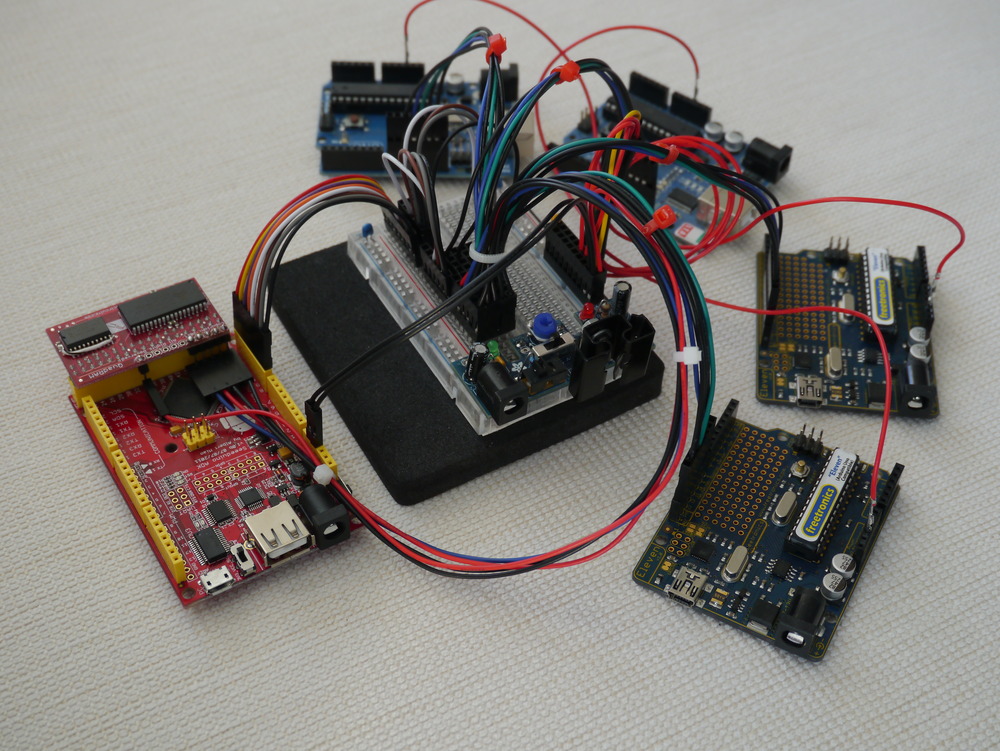
Using this prototype system, each Arduino Client node now has sole access to 32kByte of XRAMFS in addition to their 2kByte of internal RAM.
Initial performance measured is 422kByte/s throughput for the swap function. In other words, half of the entire Arduino RAM can be swapped with the contents of XRAMFS in just 4.74ms.
I’ve also the code for supporting a centralised SD Card on this platform to Sourceforge AVRfreeRTOS, and written about it at ArduSat SD Card Prototyping.
Background
In working with the Arduino hardware I’ve found that the severe limitation in RAM space causes constraints on what can be done. For example, Ethernet, USB and other modern applications need kBytes of buffer to be used effectively, and the ATmega328p used as the Arduino Uno platform supports a total of only 2kB RAM.
Using the Arduino Mega (or Android ADK hardware) has been the saviour of that situation for me, offering an identical environment, but 8kByte of RAM as a playground. And, most importantly, the ability to directly connect 0 wait-state external SRAM.
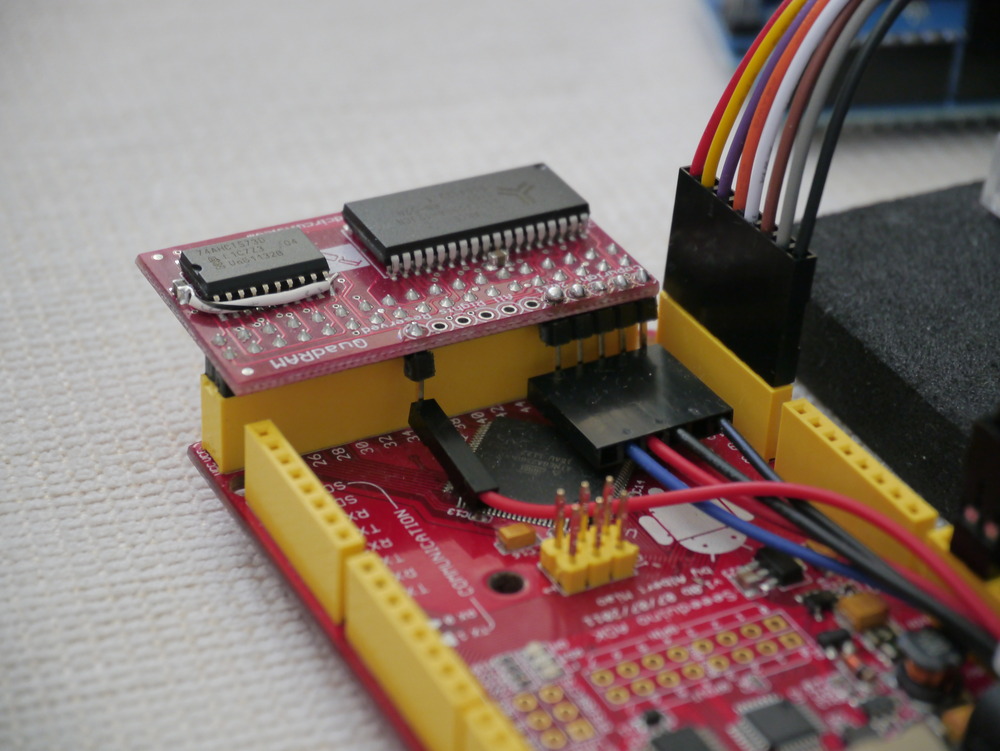
This XRAM capability of the ATmega2560 and ATmega2561 has been exploited by Rugged Circuits in their QuadRam module, which offers 512kByte of SRAM in one small package.
Therefore, using common off the shelf technology, I had the materials available to test the theory that building a XRAMFS system, to support the ArduSat platform, would work.
This allows each ArduSat Client to store 16 TIMES more data than it can currently access, and have access to that data at a relatively high speed from a medium not subject to wear (such as for example an SD card).
Ingredients & Build
This section looks at the ingredients and how to construct the prototype.
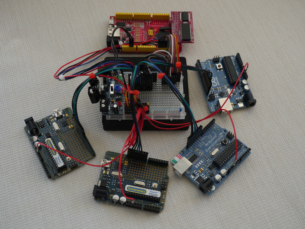
Supervisor Node – Arduino Mega / Freetronics EtherMega / Android ADK
The ArduSat Supervisor node is based on the ATmega2561 MCU, because it is significantly smaller than the ATmega2560 MCU used in the Arduino Mega platform. The only difference between the two chips is that the ATmega2561 doesn’t provide as many Ports, and has only 64 Pins versus 100 Pins on the ATmega2560.
For this prototyping, the ATmega2560 is necessary, because I elected to use pin change interrupts as part of the bus protocol. Also, the Arduino Mega platform is readily available. I don’t even know where I’d go to get a ATmega2561 board…
The use of rainbow hook-up wire was essential for the success of the prototype.
Client Node – Arduino Uno / Freetronics Eleven
The ArduSat Client node is designed to be identical to the Arduino Uno platform, to ensure that it is absolutely easy for people to test code they intend to run in space. Therefore a variety of Arduino Uno devices are being used (basically, whatever I had around).
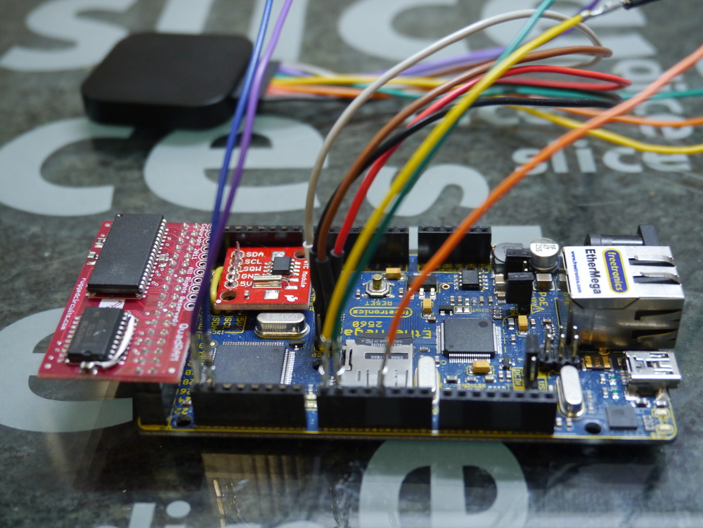
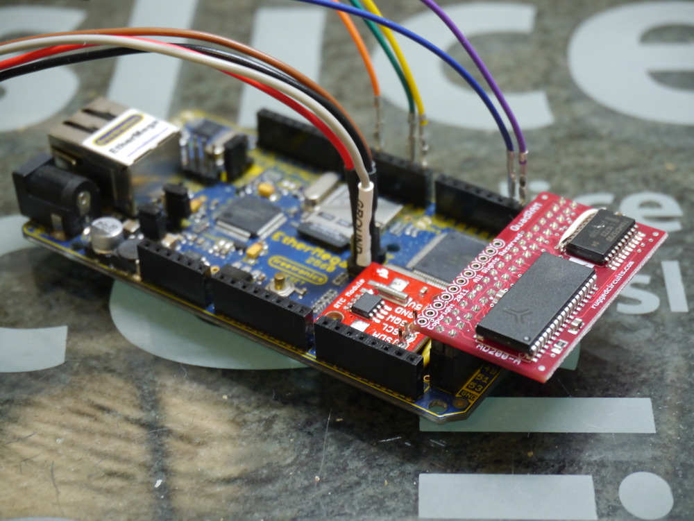
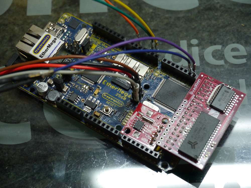
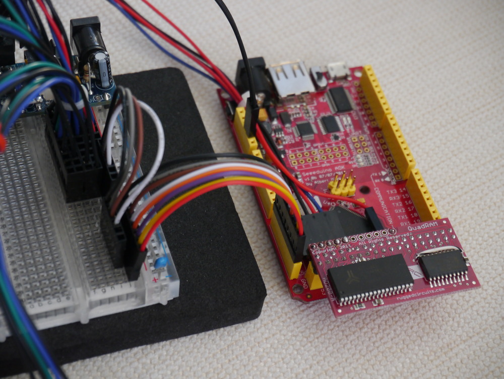
XRAM Module – Rugged Circuits QuadRAM
I’ve implemented using the Rugged Circuits QuadRAM and the MegaRAM previously. These modules slip over the end of the Arduino Mega platform, instantly enabling either 512kByte or 128kByte of zero wait state SRAM, mapped to the system address space. They also conveniently bring out the SPI interface onto through-hole for pins.

Something about the ability to create 16x 32kByte XRAM pages, linked with 16x Client nodes, seemed like synchronicity.
Layout
The prototype platform is designed to be the classic multi-slave SPI bus layout. This design is demonstrated in the AVR151 document and, in excerpt, is produced below.
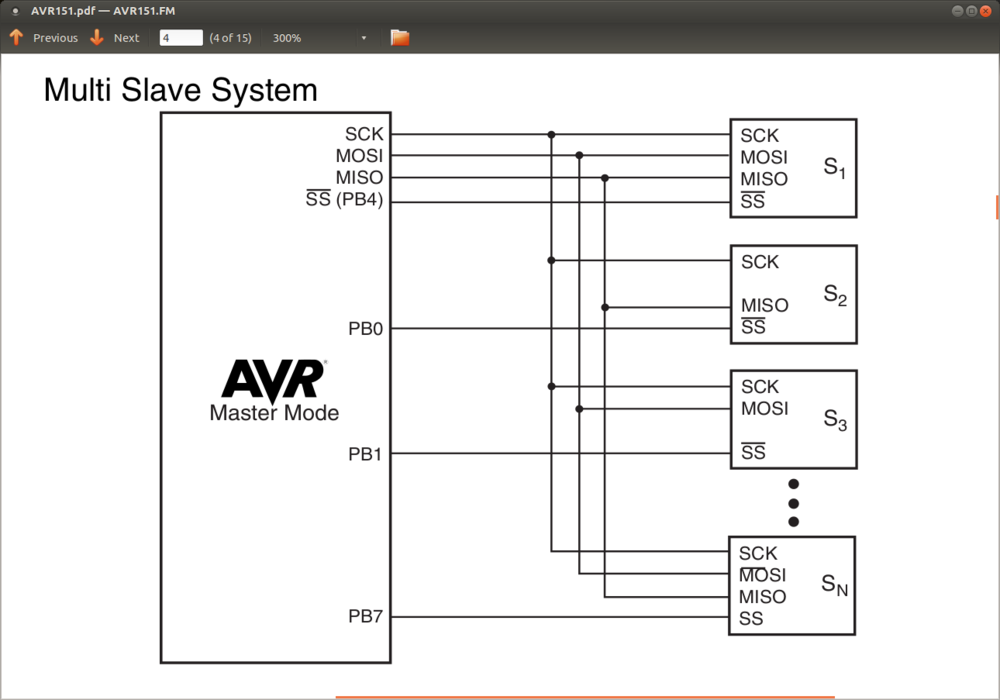
Because of my decision to use the Pin Change Interrupts as part of the bus protocol, The Supervisor node (SPI Master) would use the Port K and Port J pins to fill the role of individual Slave Select (SS) pins. The Client nodes would each use their normal SS pin (PB2) to connect to the Supervisor.
In designing for 16x Client nodes, there is a limitation on Port J in that the good folks at Arduino determined not to break out all of the pins which, together with sharing PCINT8 with the Rx0 pin, significantly limits the number of Clients feasible on the prototype platform.
In practice, 8 Client nodes attached to all the pins on Pork K is the simple alternative. As luck (or good planning) would have it, those pins are all brought out onto one connector on the Arduino Mega platform, as evidenced by these pictures.
Amongst friends, a direct connection of the SPI SCK, MISO, and MOSI lines to all Clients is optimal. But in a shared environment, it would make sense to use FET bus isolation to keep Clients from physically attaching to the SPI bus until their SS line is held low by the Supervisor. A gram of hardware prevention can cure a tonne of software ill, as a “rogue” Client could otherwise potentially lock up the SPI bus for all, and the guys in the ISS won’t be happy if asked to hit the reset button.
Bus Protocol
Hey! – Yeah What? – This! – OK
That’s the protocol. Works in the home. Works in the office. Works the world over.
Information to this Saleae Logic chart below in Client Implementation section.
Hey!
The Supervisor node holds all the PCINT pins high. If a Client wants to initiate a Read/Write/Swap transaction, it will pull its SS line low for 30µs. This needs to be long enough for the Supervisor to register an interrupt and process it. If multiple Clients call out simultaneously, no problem, the Supervisor will grab all of the requests and push them onto a queue of requests to serve.
Yeah What?
At the next opportunity, the Supervisor serving task will pop a request off the queue, and identify which Client made the request. It will also check if there were other simultaneous requests, and push them back to the front of the queue.
The Supervisor then pulls the relevant Client SS line low. The Client has been listening for this, and at this point it enables its Slave interface to the SPI bus, and the two swap acknowledgements. When the Supervisor receives the ACK code, it knows the Client is ready, so it requests a command.
This!
When the Client (SPI Slave) has received the Supervisor ACK code, it prepares a command, and is prepared to either read, write or swap XRAMFS data under the command of the Supervisor (SPI Master).
The command set implemented by this protocol can be easily extended to include accessing other shared resources connected to the Supervisor node. This could include analogue sensors, SDCARD mass storage (though using the SPI bus would offer a degree of complexity), or serial interfaced devices.
OK
At the end of one command, with the data transaction complete, a final byte is exchanged to ensure that the Client has remained in sync with the Supervisor, and the SPI bus is released by the Client. It is important the Client stays off the SPI bus. The Supervisor then processes the next Yeah What? request.
Supervisor Implementation – freeRTOS
The Supervisor is implemented as a freeRTOS task, using standard SPI bus libraries contained in my code base. These libraries (now that this project has worked them over) are about as optimised as is possible to write in C, and achieve a good throughput over the SPI bus.
There are two (or one) PCINT based Interrupt that reads the PCINT pins and pushes the raw pin state onto a queue. This process traps multiple simultaneous requests, overcoming any interrupt masking or race conditions. Currently 30µs are allowed for the interrupts to execute. 10µs has been tested, but depending on how long the Supervisor stays in “Critical” state (interrupts off) processing other (non XRAMFS) tasks this time can be adjusted.
From idle, the Supervisor takes only 90µs to 0.1ms to pop a request from the queue and action it. Under load, it could take as long as 64ms to action a request. As soon as the pin state is collected it is processed to identify which SS line triggered the call, and therefore which bank of XRAM should be enabled. Also, at this time I check that no additional requests are pending from the same pin state. If so, the remaining pin state is pushed back on the queue to get next time round.
The exchange of acknowledgements ensures that both sides are speaking SPI, and are set to proceed.
The command contains the action (read / write / swap / test), the address of the XRAMFS block, the size of the XRAMFS block, and a CRC byte.
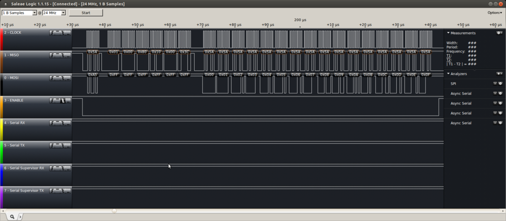
The bus transaction speed is dependent on the SPI Master SCK clock divisor. Optimally, a SPI Slave can receive data at 1/4th of its system clock. Currently, it is set to one 1/8th, therefore theoretical performance is double that of the logic capture above.
Initially, I determined to calculate a CRC byte to store along with the data, but the calculation time is large compared to the transaction time, and therefore too costly to implement at the protocol level. The application should utilise the CRC when it recovers data to confirm that the data is intact, and not irradiated.
Also, error checking following the transfer could be implemented. But at this stage I think it is better to have the Client do all sanity and error checking of its own data.
Client Implementation – freeRTOS or Arduino IDE
The Client is implemented in freeRTOS as a simple library function, that is passed a command structure, and a pointer to local RAM to be Read/Write/Swap. Some details below.
typedef enum { Huh        = 0, // Client didn't issue us a command, so just break.
               Read       = 1, // read from XRAMFS
               Write      = 2, // write to XRAMFS
               Swap       = 3, // read from both XRAMFS & local RAM, and swap
               Test       = 4  // do something else, to be determined
} RAMFSCommand; // from point of view of the client (Arduino 328p)

typedef struct        /* structure to hold the RAMFS info */
{ RAMFSCommand       ram_cmd;        // Read / Write / Swap / Test
  size_t             ram_addr;       // Address of first byte of RAM in a RAMFS (greater than RAM_START_ADDR)
  uint16_t           ram_size;       // Size of RAM block in RAMFS (less than RAM_COUNT or 32kByte)
  uint8_t            ram_crc8;       // Calculated CRC of stored data
} xRAMFSarray, * pRAMFSarray;

uint8_t ramfs_transfer_block( pRAMFSarray pRAMFS_block, uint8_t *data );
I used C and the freeRTOS platform because it is easiest for my environment, and I know it best. But, I’ll re-write it as a library in the Arduino IDE environment as needed. It won’t be too hard.
The client can use the XRAMFS malloc function to manage RAM allocation. A very simple malloc has been built, which can’t free XRAMFS. But, it can be simply ignored if desired and the command structure can be filled manually.
Initially, I implemented an interrupt driven semaphore system to manage the Yeah What? part of the bus protocol, but typically the Supervisor responds so quickly that the time to do several context swaps generated by the interrupt exceeded the time the Supervisor was prepared to wait. A simple wait loop keeps the Client on ready standby for 90µs so it can complete the transaction in the shortest time.
The Client code has no knowledge of where its XRAM is located on the Supervisor. Therefore the code is orthogonal and constant, irrespective which Client being used. This is a very useful feature where the author may not know in advance which ArduSat Client his code will be running upon.
Client application code should be written to make use of the Swap XRAMFS <-> RAM capability. This makes best use of the SPI bus features to combine Read and Write into one transaction, effectively doubling throughput over the Write plus Read combination.
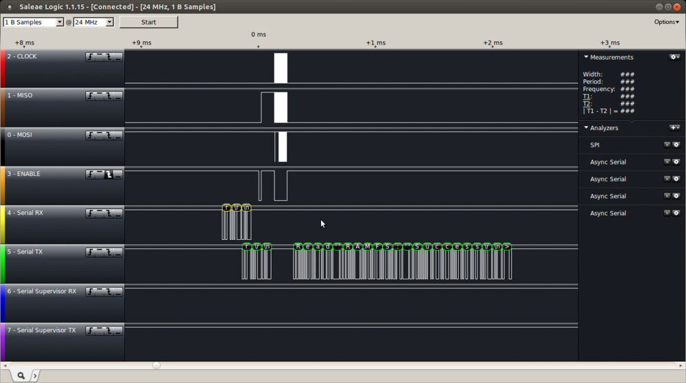
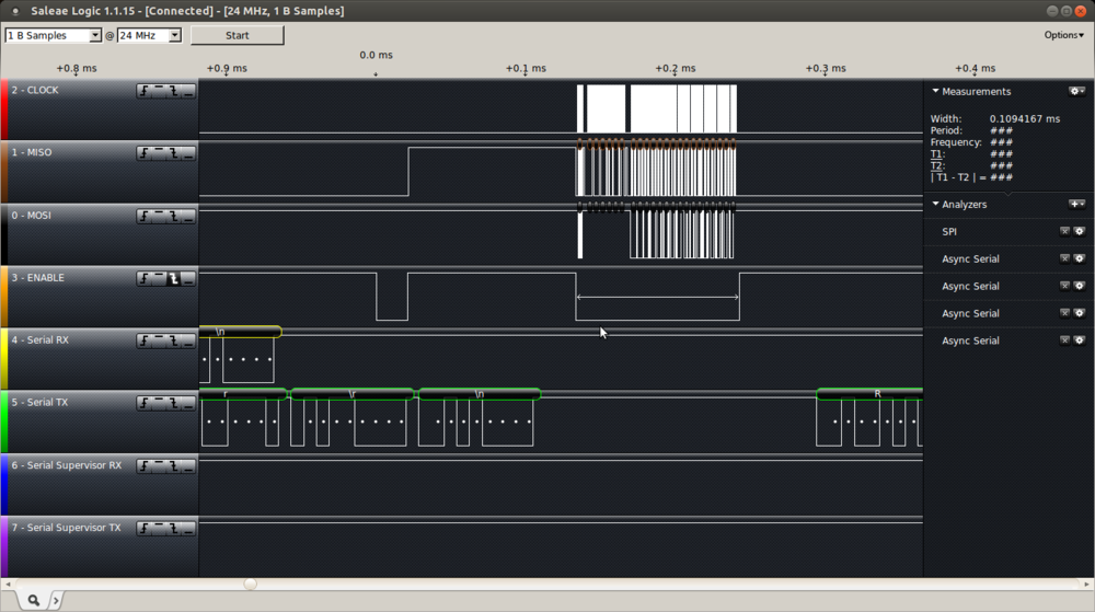
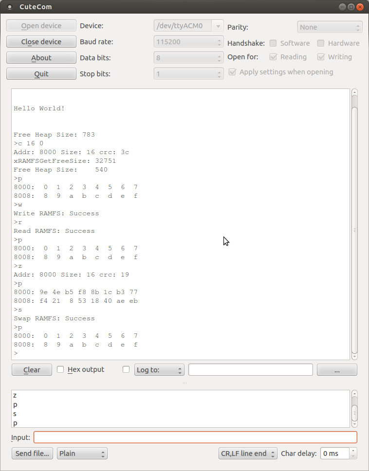
The user interface (monitor) is just for initial testing. I’ll have to write a load generation rig to find out what this baby can do, but that can wait for the next post. The logic analyser has captured the result of the > r (read) command in the below command line sequence. We can see the 20µs (now 30µs) Hey! on the Slave Select, 90µs pass before the acknowledgement bytes are swapped (only one cycle needed), 6 bytes of command structure are passed (Read command is 0x01), and then the data is read out of XRAMFS to the Client.
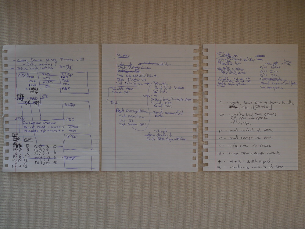
Design Notes
The basis of every design: detailed functional specifications, hardware design, and user interface documentation. Oh, and scribbles much.
Updates
I’ve updated the code on 22 February to remove some oversights in the Client main program, and added the OK check byte to the protocol. Code as usual on AVRfreeRTOS on Sourceforge.
Updated on 23 February to include some error checking on Supervisor side (preventing malicious Client requests), and on Client side preventing hang if the Supervisor is AWOL. Also removed the aggressive SPI timing utilising receive double buffering, as it often caused errors, and had no performance effect.
Initial performance measured is about 422kByte/s throughput for the swap function. Specifically 4.73825ms is needed for a complete 2048Byte data payload transaction (including sync, command, & OK timing). This also includes freeRTOS task swapping, as the Supervisor task is run with interrupts enabled in normal mode.
Have fixed some code issues on 4 March, mainly around a few µs delays required to let things run their course.
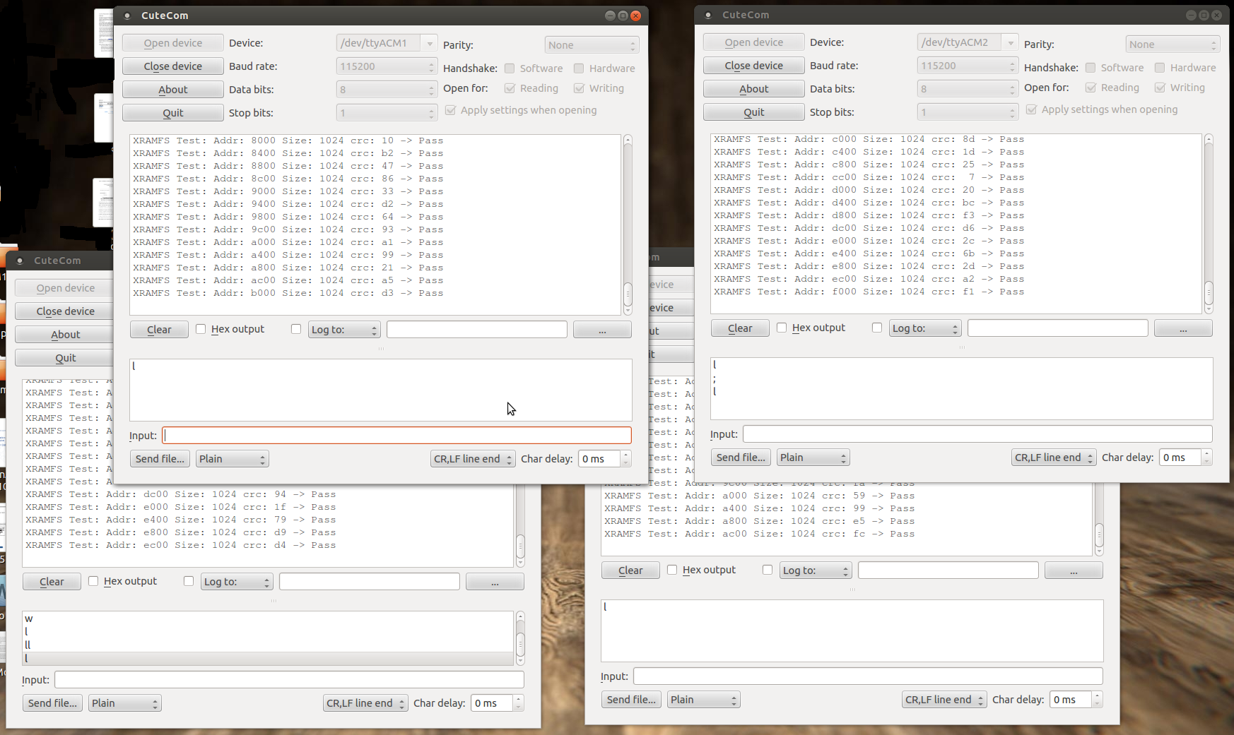
Now the platform is running stable with 4x Clients. A video is here
And here is a screenshot of the 4x terminals.
April 27th – I’ve uploaded the code for supporting a centralised SD Card on this platform to Sourceforge AVRfreeRTOS, and written about it at ArduSat SD Card Prototyping.