It seems that the Wiznet W5100 Ethernet Shield has been around since the very beginning of the Arduino movement. Its integrated TCP and UDP IP stack enabling solid standardised networking since the very beginning.
The hardware implementation of BSD sockets interface abstracted the complex process of generating compliant IP and made sure that it was done correctly, and the buffering of network packets in integrated packet RAM, rather than on the host AVR micro-controller; was a great thing when you only have 1kB of RAM available as the original ATmega168 Arduino devices provided. For the current generation of Arduino devices, nothing has really changed.
Recently, I wrote about the new W5200 iteration of the Wiznet integrated IP controller, and how it is significantly better in performance and features than the older W5100 version.
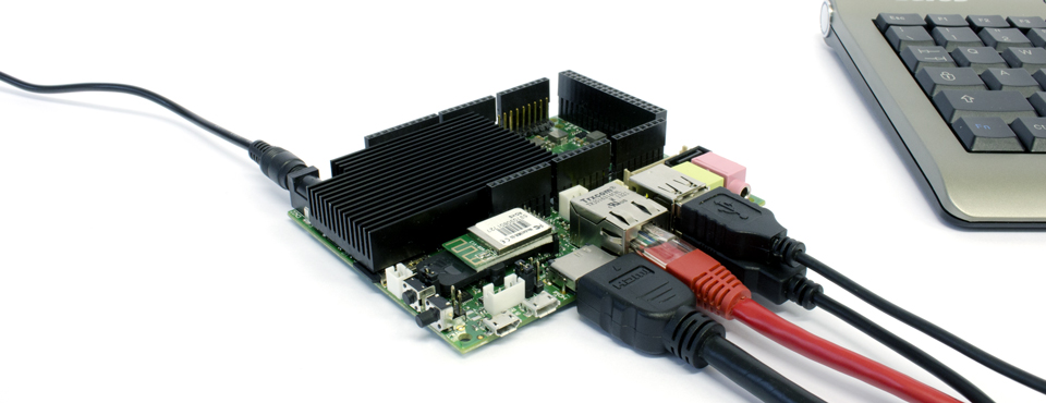
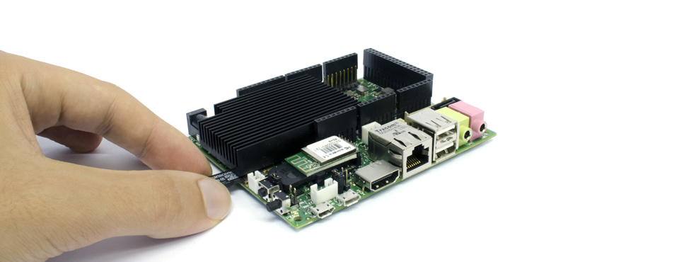
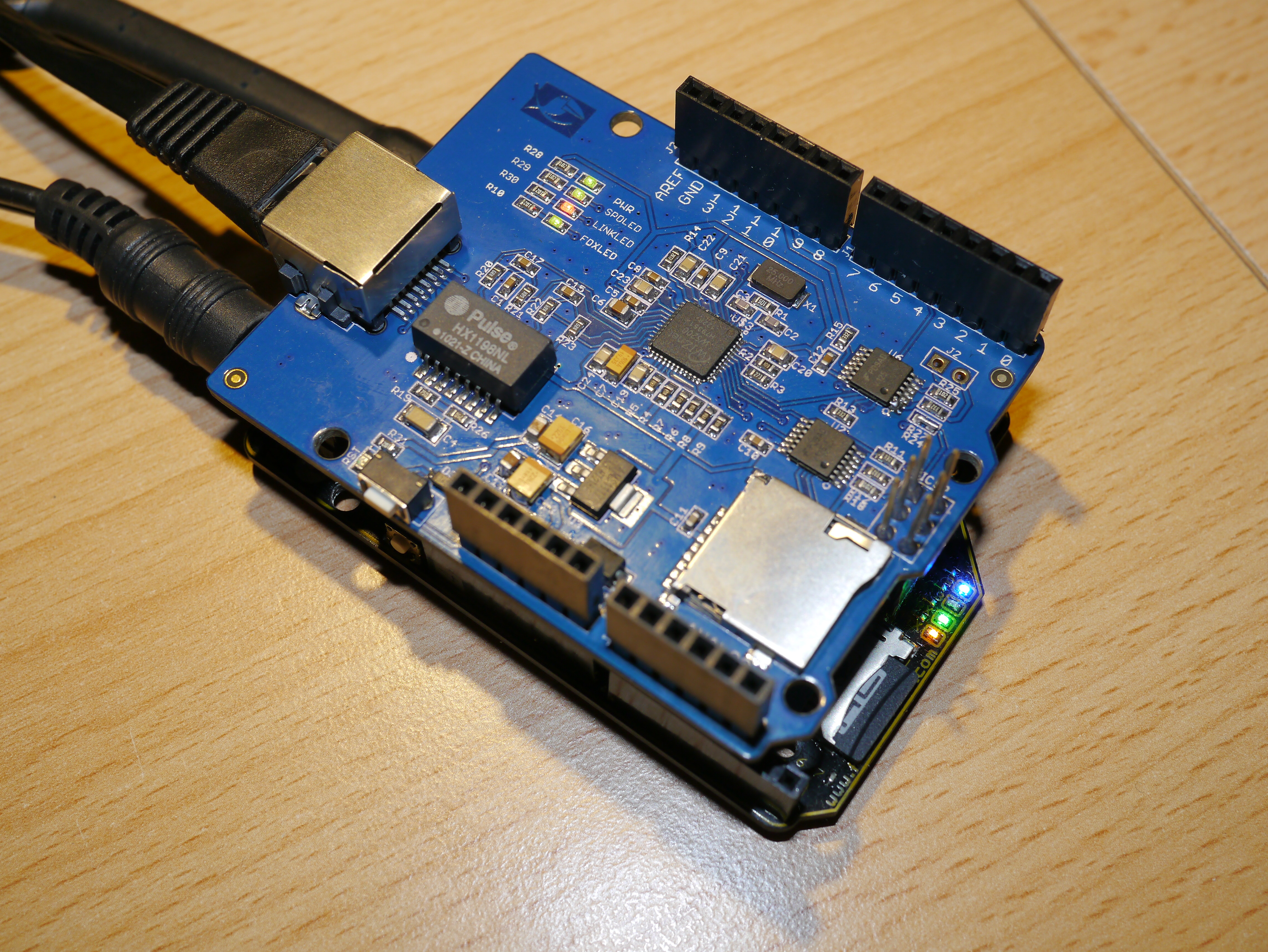
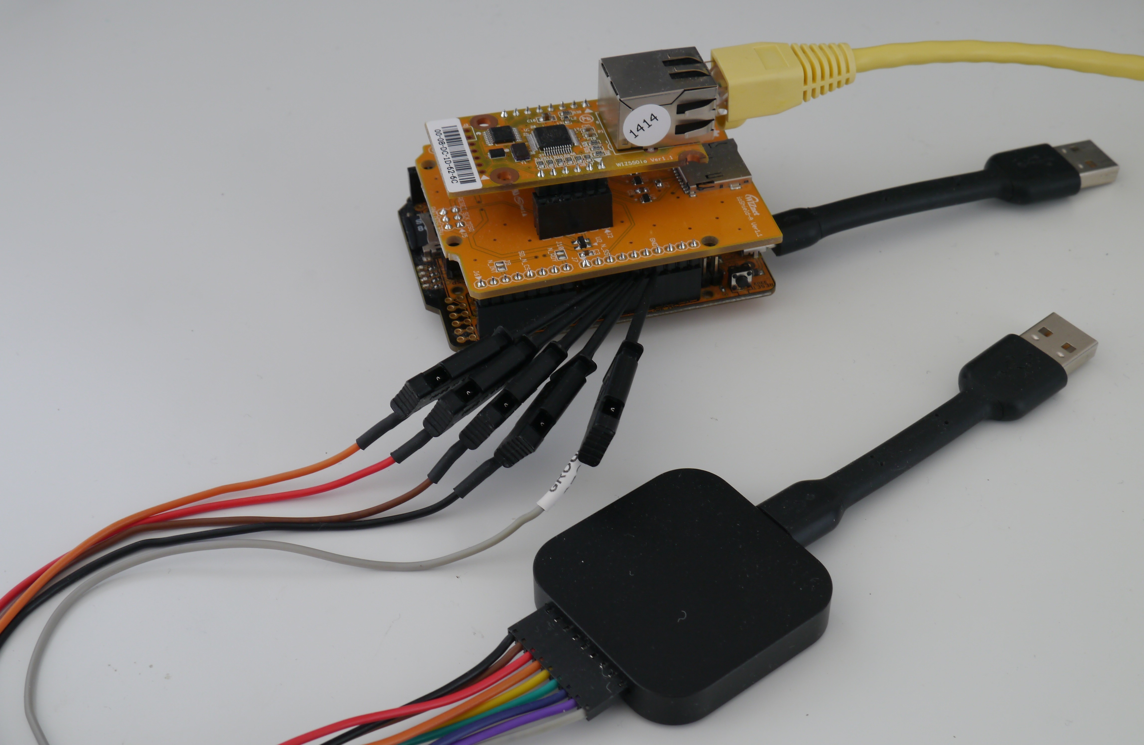
Now, I have my hands on the latest version. The W5500 on an ioShield-A from Wiznet.

W5500 on ioShield-A from Wiznet
TL;DR. The W5500 is the latest and best iteration of hardware IP socket Ethernet devices from Wiznet, and also the easiest for hobbyists to implement. As usual, my code is here at AVRfreeRTOS.
So what are the key differences between the models, and how do they perform? I’ll try to look at three important aspects to using these devices; cost, implementation or how are they to use, and performance.
Cost
As Wiznet has iterated through the W5x00 series it has cost reduced the manufacturing significantly. The W5100 was produced in 0.18um process, as was the W5200. The new W5500 is produced in 0.13um process, with a 1.2v core, in comparison. Between the W5100 and W5200 Wiznet doubled the size of the internal packet RAM to 16kByte, but significantly reduced the number of IO pins and drivers, to make the W5200 (and W5500) SPI bus specialists.
The result of these cost reduction processes can be seen in the pricing information from Digikey. The price per 1,000 for W5100 is $4.32 each, whereas the W5500 is $2.64 each. In a commercial project, or even a significant crowd funded project, this can have a significant impact on the bill of materials.

Digikey W5100 Pricing

Digikey W5200 Pricing

Digikey W5500 Pricing
Implementation
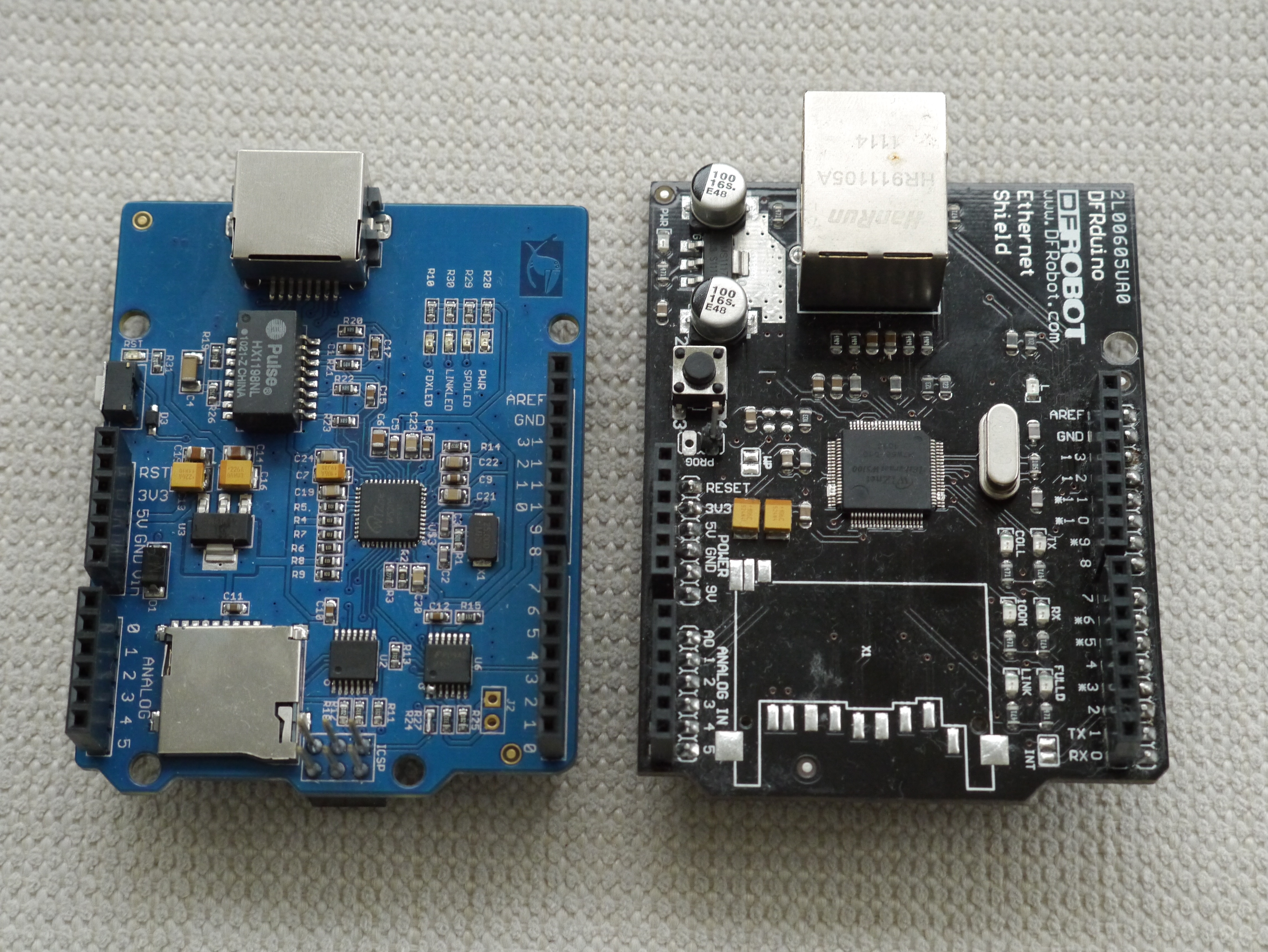
The W5500 is available in 48LQFP which is aimed squarely at low tech solutions. The W5200 was only available in 48QFN which made it more difficult to use the chip in low volume applications. While most people will purchase the W5500 on an Arduino Shield or similar platform, having the LQFP package does make it easier for the companies producing the Shields and modules for the hobbyist.
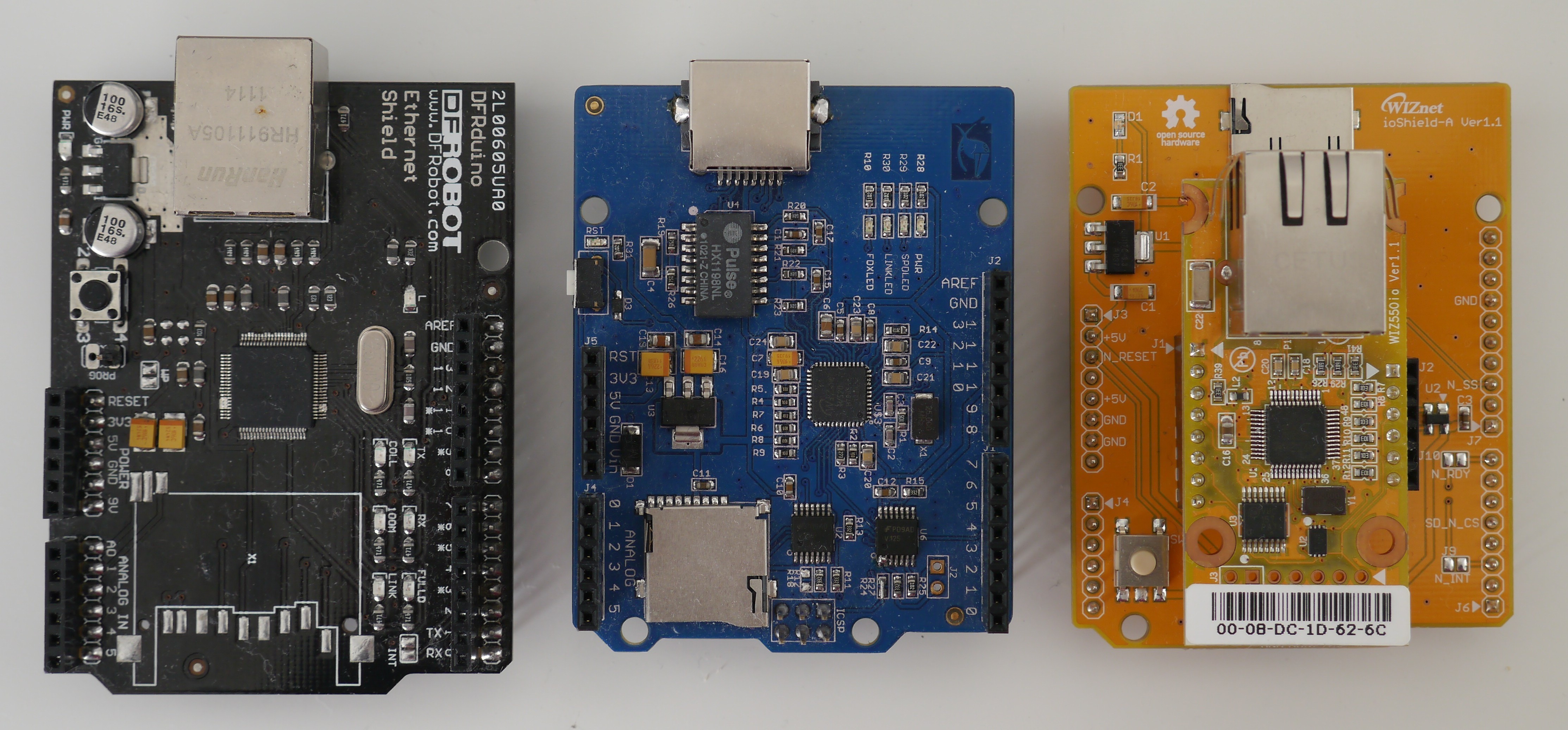
The three Wiznet W5x00 Generations
In terms of implementation differences between the W5100 and the W5200, I’ve already written on the extensive improvements to the SPI bus interface, both in terms of outright speed, and in the protocol improvements, doubling the packet RAM to 16kBytes, and doubling the number of sockets available to 8. The W5500 takes these improvements and finesses them to get an even better result.
Wiznet have prepared a summary of the differences between W5500 and W5200. The SPI protocol for the W5500 has been simplified, omitting the frame length field. The end of transmission is simply indicated by deselecting the chip with the SPI Chip Select line. This is an obvious and simple improvement.
The packet RAM on the W5500 has been made available as general storage for the host MCU. Both Tx and Rx RAM is available for use as required. This means that it is possible to augment the RAM on an Arduino Uno by 16kBytes (8kB Tx and 8kB Rx) which is 8x more than the ATmega328p has in total, and still maintain the same sized buffers available in the W5100, for example.
The Tx and Rx RAM is arranged in blocks associated with the socket, and the entire 16 bit address space is rolled out onto the configured RAM for each socket. This means that when writing or reading the W5500 Tx and Rx RAM the user doesn’t need to be concerned with masking the maximum physical RAM, and addressing roll-over is gracefully handled. This is unlike the W5100 and W5200, where RAM addressing would have to be masked against the configured physical RAM. If this sounds complicated, just check the datasheet where it is explained in a nice diagram.
For use in the Arduino IDE environment Wiznet has prepared W5500 drivers which can simply be copied into the IDE directory structure and used as needed. For general implementations, Wiznet have prepared a new generation BSD Sockets based Socket driver which is much more flexible and better written than the previous iteration.
I’ve implemented my code based on the Wiznet transition driver, which maintains the legacy BSD Socket style interface used in W5100 and in W5200. That way I can maintain one socket.h and socket.c code base as an interface, and simply use the relevant hardware driver W5x00.h and W5x00.c as required. I was pleased that in taking this path, Internet code that I’ve written previously “just worked”. This included the hardware sockets dhcp (using IPRAW), ntp, http interfaces which work with the W5500 protocol engine, and the uIP implementation that uses the MACRAW mode inherent in all three devices.
Of note is the resolution of the errata in the ARP engine, which required off device storage of the subnet mask in some situations, which affected both W5100 and W5200. With the W5500 Wiznet have put that issue behind them. I imagine that many other issues and inefficiencies in the hardware socket engine have been redesigned and resolved in the W5500 too.
Performance
The performance improvements of the W5200 over the W5100 have been documented, and the enormous throughput improvement obtained by using the streaming SPI Interface shown.
While the W5500 does implement an improvement in the SPI interface, by removing the data length selection field, there is no noticeable improvement in throughput over the W5200 using an AVR ATmega1284p Goldilocks as the platform.
One design goal for the W5500 seems to have been to make the SPI interface much more friendly for 32 bit processors, particularly Cortex M0+ MCU with limited RAM, by packing the addressing, and control information into one 32 bit (4 x 8bits) register. It is possible to imagine that there are additional performance improvements in the SPI interface if driven close to its design maximum SCK of 80MHz, rather than at the lowly SCK rate of 11.05MHz off the Goldilocks platform.
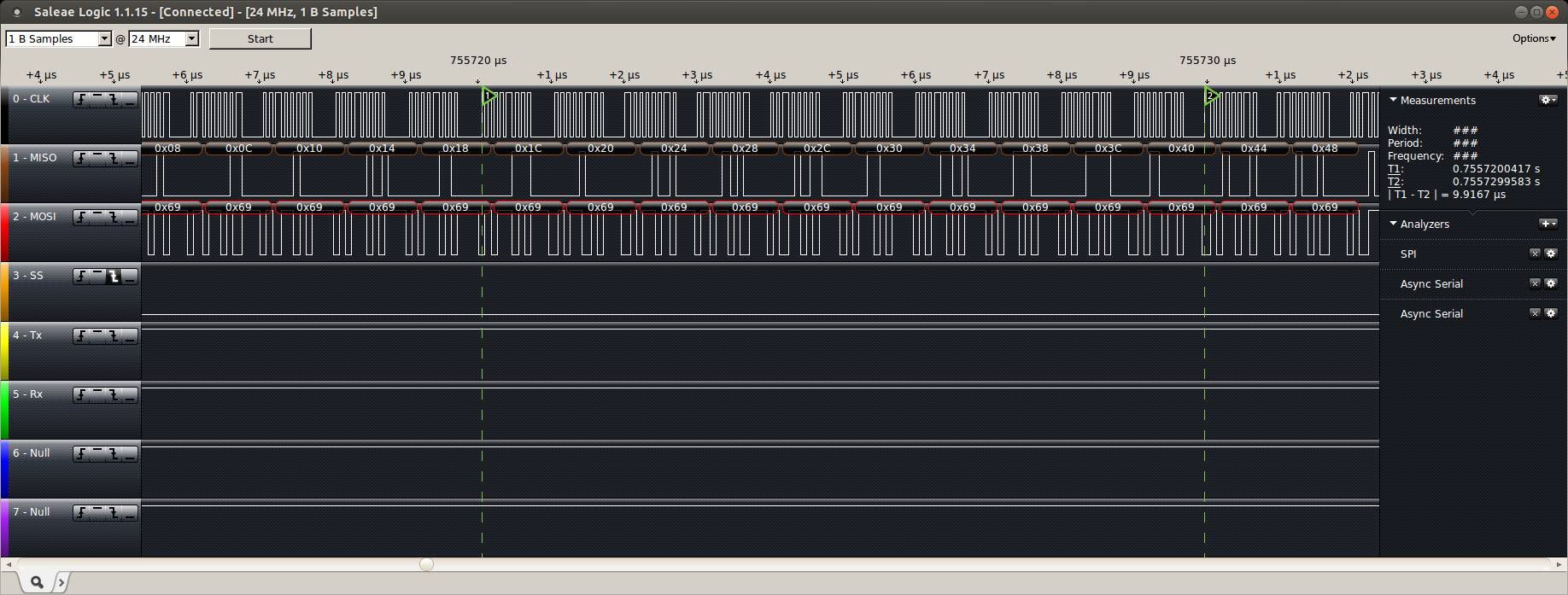
Testing W5500 SPI throughput with Saleae Logic on the Goldilocks ATmega1284p
I compared the W5500 running uIP in MACRAW mode to the W5200 running identical (except for the driver) code and using the ping function to test how quickly the SPI interface can transfer a received packet to the host MCU, and then transfer the processed packet back to the W5x00 buffer for transmission.
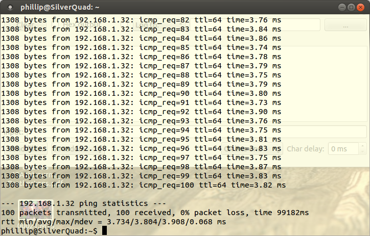
The ping results were slightly slower than previously seen on the w5200. But I believe that is an external issue, possibly resulting from a change in my network. I have repeated the test with the W5200, and now get similar performance too. I believe I may have some network issues to resolve.
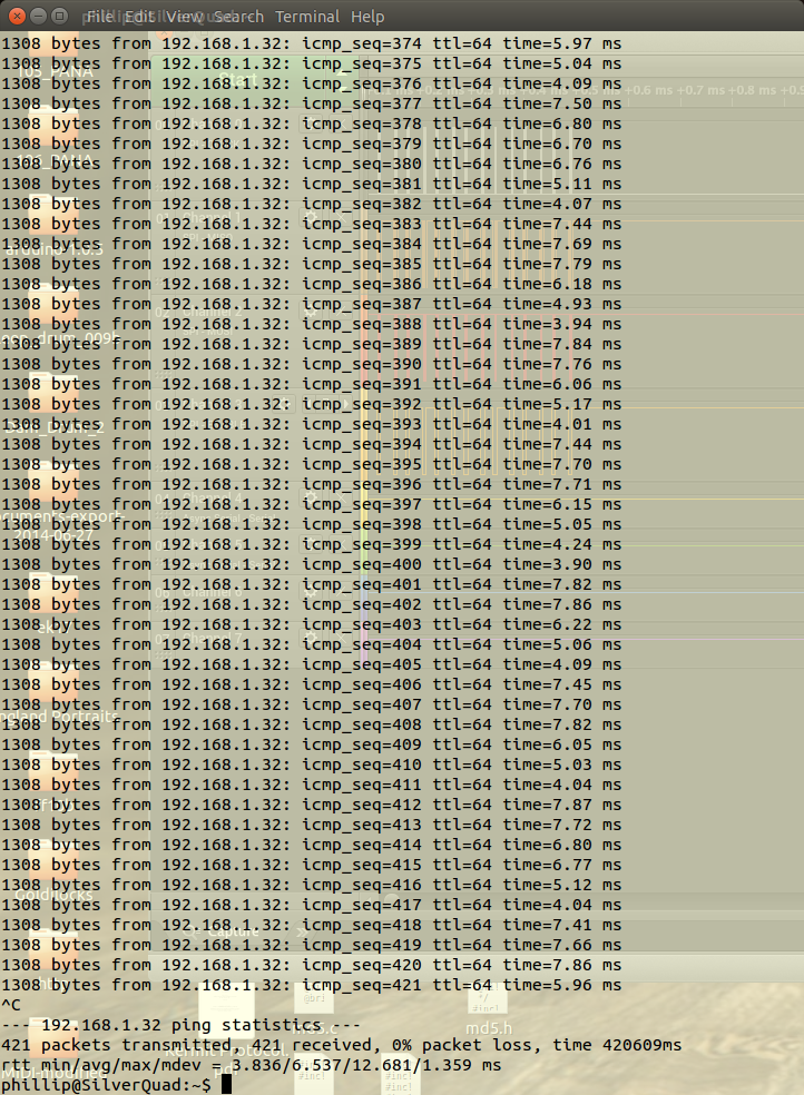
1300 Byte ping packet transmitted from a host to the W5500 interface running uIP in MACRAW mode.
Looking at the output of the Saleae Logic and comparing the time taken to transfer the Ethernet frame into the host MCU, we can see that the time required to transfer the 1300 Byte frame is almost identical at 1.52ms.
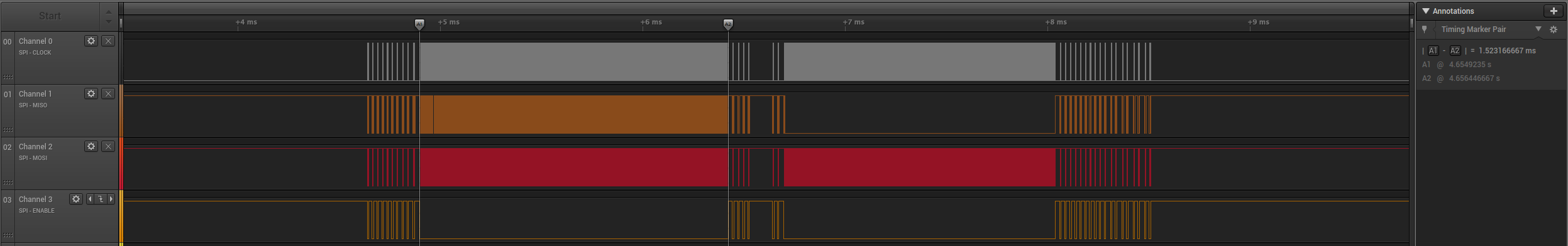
W5500 Rx Ethernet Frame transfer to the ATmega1284p

W5200 Rx Ethernet Frame transfer to the ATmega1284p
Not surprisingly, the time to process the frame, and produce a response frame are also identical.
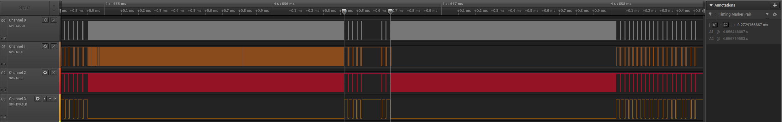
Ethernet Frame processing on the AVR1284p (W5500)
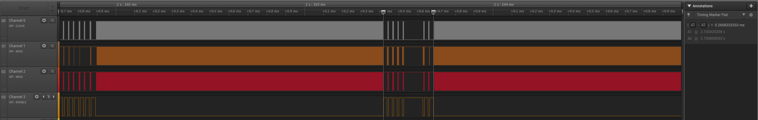
Ethernet Frame processing on the AVR1284p (W5200)
Conclusion
The W5500 chip is an improved version of the W5200, which was a greatly improved version of the W5100 device. It is a welcome new addition to a long heritage of IP protocol engines from Wiznet.
I think that the improved implementation in 48LQFP packaging and reduced supporting device count will make it easier for hobbyists and low volume manufacturers to generate great Internet tools off the Arduino and small ARM MCU platforms. We’re starting to see some implementations already.
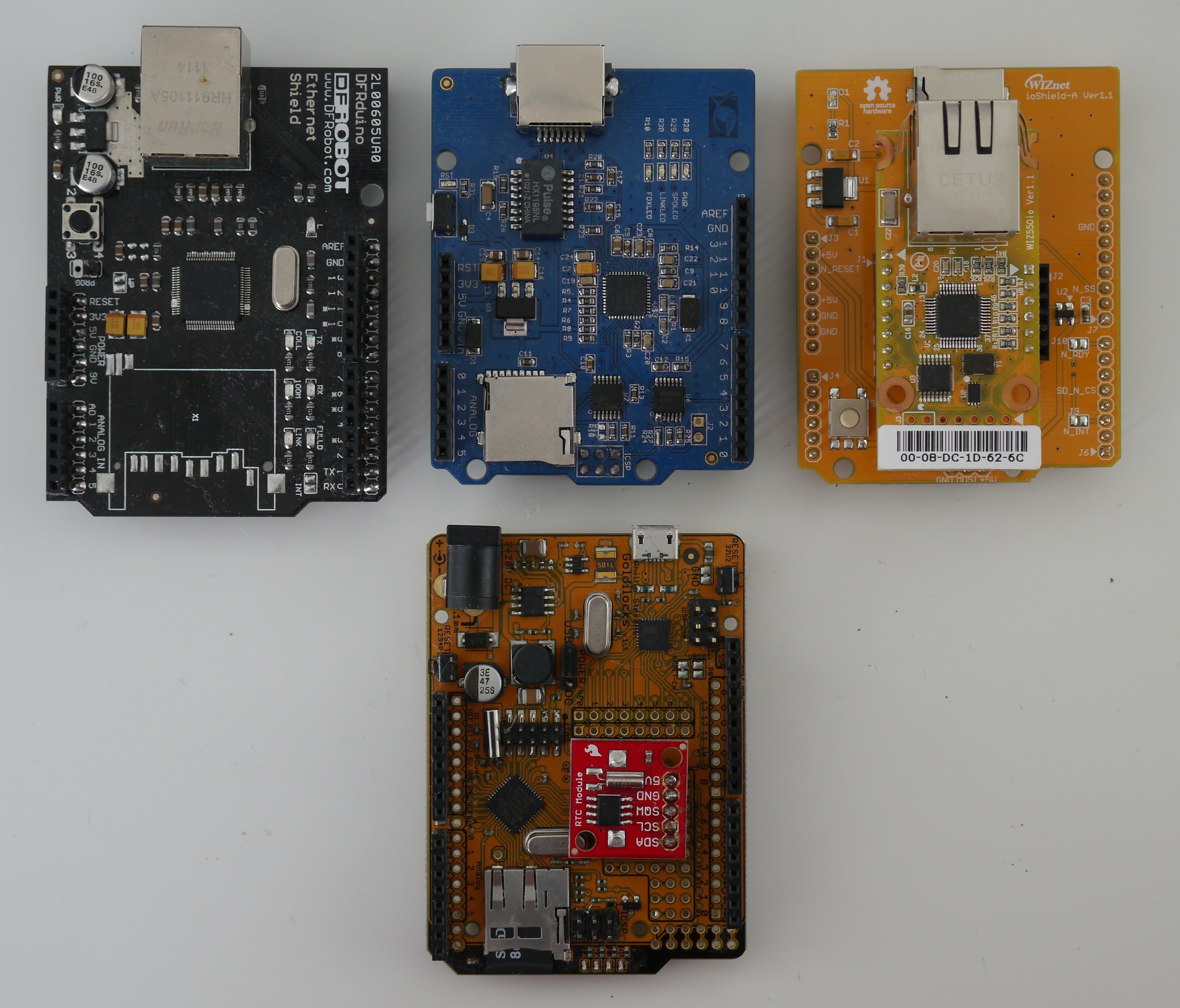
Three generations of Wiznet Internet Protocol Devices. Goldilocks 1284p for scale.
As usual, my code is here at AVRfreeRTOS in the lib_iinchip folder.
Wiznet have made this post Treasure #14.