
I guess it is no secret, the reason why I’ve put so much effort into getting the Goldilocks 1284p board built. I was looking for a platform that would allow me to experiment with the uIP TCP/IP and UDP/IP stack with the most performance and flexibility possible while still being compatible with the huge range of sensors and actuator Shields that form the Arduino legacy. From the microprocessor view, the ATmega1284p used in the Goldilocks certainly achieves that goal.
I’ve written in a previous post about the theoretical performance difference between the common Wiznet (or IINChip) W5100 used in almost all Arduino Ethernet shields and the component I have selected that uses the W5200 to provide the Ethernet interface. This post demonstrates the real world performance differential with a simple example.
Recently, I’ve been working with the W5500 on a ioShield-A.
But first, I am happy with the result of the uIP port to the Wiznet platform within freeRTOS. I’ve taken some of the old uIP v0.9 and v1.0 files from many sources, and updated them with the latest snapshot status from Contiki 2.7, to try to bring the last 5 years of experience into the result. Whilst the resulting codebase has not as yet been extensively tested, it seems to work as expected.
Results
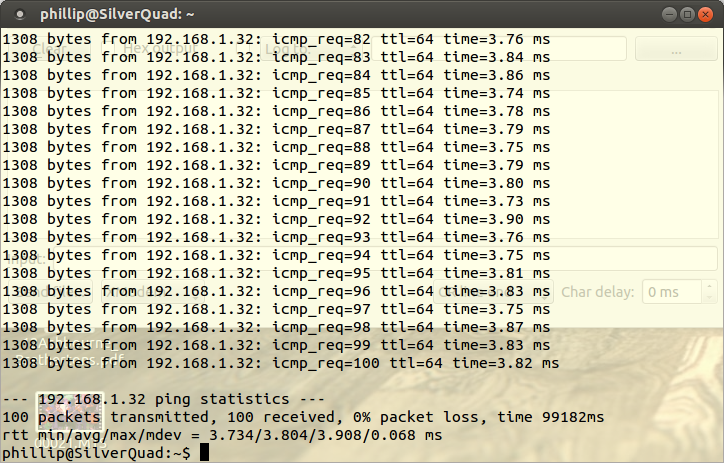
This is a simple test, sending 1300 byte PING packets to the MACRAW interface on the IINChip to be handled by uIP. After 100 PINGs the W5200 takes on average 3.804 ms, whilst the W5100 takes on average 22.109 ms for each round trip.
This means the W5200 is nearly 6x faster than the W5100 in real world performance.

Of note, this real world result is achieved whilst over-clocking the W5100 SPI bus out of specification at 5.5MHz (being SCK/4), rather than at 4MHz which is the specification. The W5200 SPI bus can, of course, run up to 30MHz or faster, so its limits are not even being tested by the Goldilocks ATmega1284p MCU.
W5200 SPI bus
The key differential which provides the W5200 its performance advantage is the use of multi-byte burst transfer mode for moving payload data into and out-of its controlling MCU. In theory the entire 32 kByte Address space of the W5200 could be transferred in one transaction. In practice, a full Ethernet frame can be transferred in just over 1 ms.
These shots show how the W5200 SPI multi-byte transfer works in practice.

The W5200 supports multi-byte burst mode transfers on the SPI bus. This is a 1300 Byte PING frame transfer out of the W5200, and returned by the AVR.
This screenshot shows an entire received 1300 Byte payload PING frame being transferred in 1.34ms.

The AVRmega1284p generates a PING response frame, and transfers it back to the W5200 in one burst mode transfer.
The Goldilocks AVR1284p takes 0.29ms to generate the response PING, and then it is transferred back to the W5200 for transmitting on the wire.
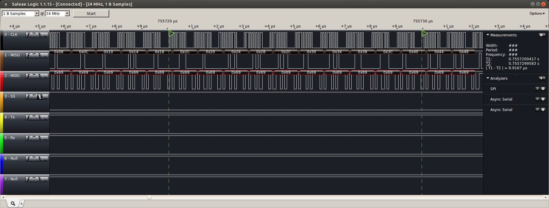
Detail of the burst mode multi-byte SPI transfer capability of the W5200.
This screenshot shows the detail of the transmission of the PING frame to the AVRmega1284p. Note that each Byte takes less than 1 us to transfer.
W5100 SPI bus
The W5100 SPI bus uses a 4 byte transaction to transfer a single payload byte, and it is not capable of a multi-byte burst mode.

The Wiznet 5100 uses a 4 byte protocol to transfer a single data payload byte.
This screenshot shows the detail of the transmission between the AVRmega1284p and the W5100. It shows that to transfer 1 payload byte it takes about 0.036 ms (which is 36 us or 36x longer than the equivalent transfer on the W5200).
Conclusion
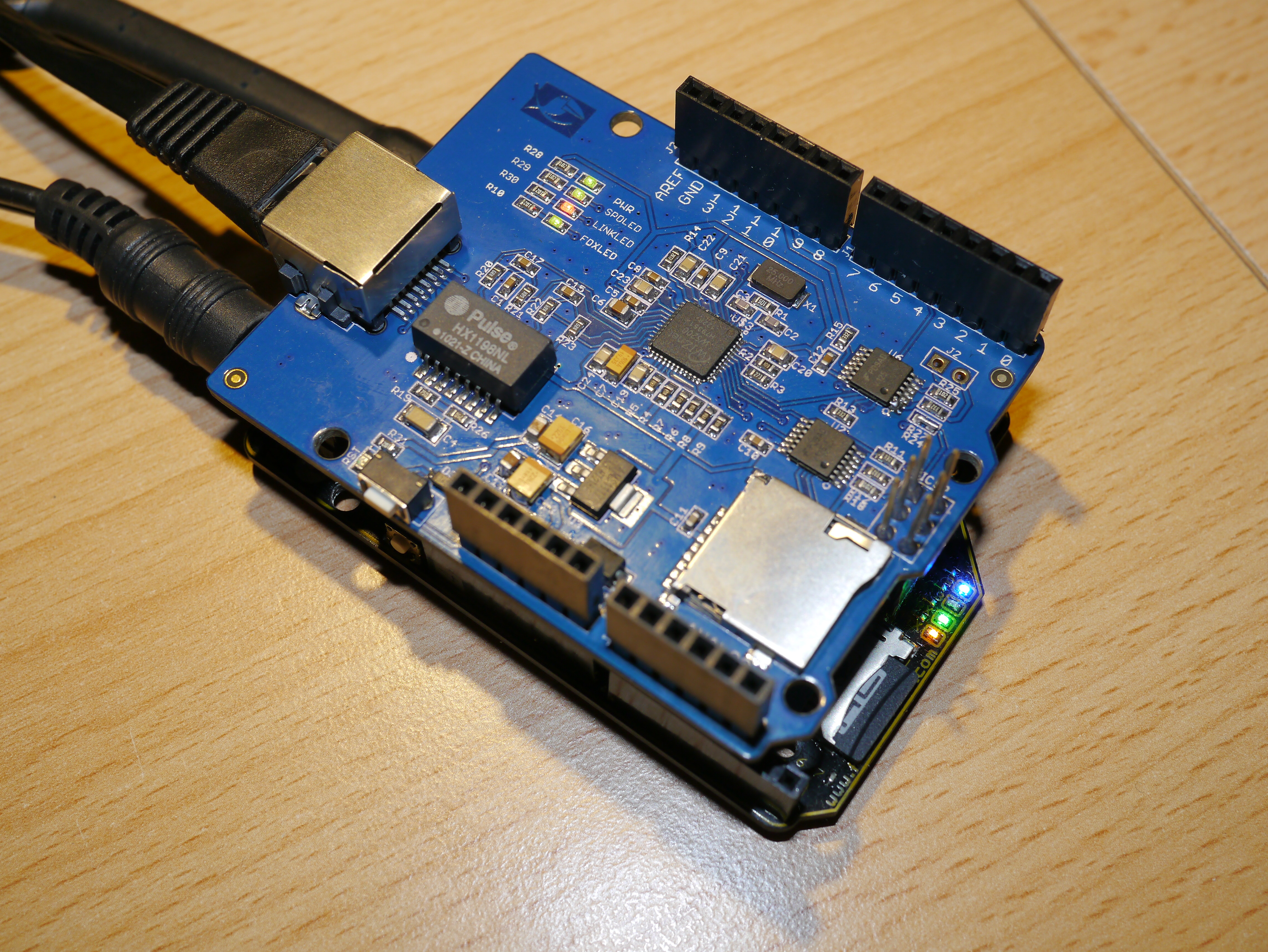 If you’re planning on building anything that relies on wired Ethernet, then go out of your way to find a Elecrow W5200 Shield or Seeed W5200 Shield. It is about six times faster than the common W5100 in the real world testing, and has many other great features.
uIP works well on the Goldilocks and provides a great platform for developing TCP/IP and UDP/IP stack applications.
Next steps are to implement CoAP and MQTT clients on this platform, to increase my understanding of both of these important IoT protocols.
Code, as usual, on Sourceforge.

I’m playing around MAC-RAW mode with W5200, but having some problems. Have you found real differences with W5100 in the handling such data? From the datasheet looks not.
Dario, I found it behaves as noted in the datasheet. Have a look at the code on sourceforge though. It should be pretty straightforward. I’ve been tied up with other projects for past few months, so haven’t done much work with uIP, unfortunately. Have a look at the W5500 though, if you’re designing a new board. I’d be doing that for the next iteration. Regards, P
I’m having some problem while using the W5200 in MAC-RAW but found no difference on datasheet on this mode if compared to W5100. Have you experienced issue about?
Pingback: Wiznet W5200 Arduino Shield by Elecrow | feilipu
A lame question. Since the wiznet chip already provides the TCP/IP stack why do you want to use the uIP?
cidadao, there are a few reasons for implementing uIP on the Wiznet chip, not least the adventurer’s claim: “because it is there!”. The MACRAW feature of the Wiznet chips is there to support non IPv4 protocol stack implementations using the chip set, and to support additional protocol implementations running alongside the standard IPv4 hardware stack.
I used uIP, because I wanted to learn a little more about this very well written and supported IP stack. I was also intending to do some work with IPv6, which uIP supports and the Wiznet hardware doesn’t support. Using uIP and the MACRAW software option gives you the option to experiment with the protocols and to change things as you want.
Another reason to use the MACRAW mode and a software IP stack is where you need to have more than 4 (W5100) or 8 (W5200) ports open at once on your solution. Doesn’t happen often, but you might want to run a number of services (NTP, DHCP, FTP, HTTP, Telnet, etc) concurrently. The software stack option is recommended by Wiznet, for this very situation.
For normal usage it is probably best to use the standard hardware stack on the W5100/W5200. The Wiznet drivers are very well supported, and I’ve also used them for a number of projects.
Dear feilipu,
WIZnet have released a new product W5500, and make module like Ethernet shield named “ioShield-A”. Do you have some interest about that? if you have, I can send free sample to you. if you want, please send email me.
Oh, I missing. first, I’m very interested in your posting. Thank you for posting.
Bong Jun,
Yes. Very interested. Thank you.
I will send you an email.
Pingback: Wiznet W5500 and ioShield-A. What’s old is new again! | feilipu
Pingback: WIZ珍藏 #2:来自Elecrow的 WIZnet W5200 Arduino Shield
this statement has a typo, it should be W5100 instead of W5200: “…. average 3.804 ms, whilst the W5200 takes on average 22.109 ms for each round trip.”
Feilipu please can you help me?
I own a W5100 ethernet shield and Im using arduino MEGA with it.
But I also use a nRF24L01 module and as we know the W5100 “dominate” the SPI and I have to use SoftSPI on the nRF24L01.
You know if W5200 or W5500 can solve my problem? Maybe I can use Hardware SPI with ethernet module and nRF24L01 as expected?
Thank you!
Raphael Trajano
Raphael,
Yes, both the W5200 and the W5500 devices properly free the SPI bus when deselected. You should be right with either of them.
IIRC, You need to transmit 1 byte or actually 8 SPI clocks to them to allow them to complete the bus free process, before you select the next SPI device.
Good luck.
Thank you feilipu! =D