
This is the final item on the Goldilocks Analogue as a design and production exercise.
Thank you for pledging on the Kickstarter Project page. Closed on November 19th 2015, with 124% funding. Now that the Kickstarter Pledges have been shipped, the Goldilocks Analogue is available on Tindie.


I’ve been updating this post with the pre-production and production experience over the past few months.
The pre-production design materials, correcting the errata noted on Prototype Version 4, have been finalised and sent to Seeed Studio.
GoldilocksAnalogue_Seeed_20151120
The interim backer report is out, and now manufacturing quantities for procuring parts ready for the February production run have been finalised.
An updated version of the Goldilocks Analogue User Manual is available, and the Production Testing Document has reached Version 2 following inclusion of Windows 10 test procedures.
Revised Arduino IDE Variant files for Goldilocks Analogue using the Arduino core are available on Github.
Also additional optional libraries to provide support for each of the advanced features of the Goldilocks Analogue are available in the Arduino IDE Library Manager.
- DAC Library (including IIR Filtering), using Timer 3.
- SPI SRAM and SPI EEPROM Library (including Ring Buffer solution).
- C90 Real Time Clock Library, using Timer 2.
- FreeRTOS Library, using the Watchdog Timer.
Arduino IDE compatibility testing revealed only a few remaining issues related to support of the ATmega1284p used in the Goldilocks Analogue. Two issues have been raised and resolved as 2 pull requests on the main Arduino IDE development path.
- The ATmega1284p has two 16 bit timers that can be used to control Servos. So the configuration of ServoTimers.h was adjusted to add support of Timer 3.
- In the SD Card Library, the hardware SPI interface was linked to a limited set pin assignments contained within the library, rather than referring to the relevant pins_arduino.h or the variant.h file suiting the board selection. So the SPI pins defined in the Sd2Card.h header file are assigned from pins_arduino.h rather than those arrived at in the SD2PinMap.h method for Software SPI.
Both these issues have been committed into the Arduino main git tree, and they have landed in Arduino IDE Release 1.6.8.
The only remaining known issue is the limitation in the configuration of the Tones() code to use only Timer 2. We would like to use Timer 2 for the RTC. There is no other option but to use this Timer for the RTC support, so it would be good if Tones() could be configured to use a different timer.
Testing
Rather than going back over old ground, I’ll just be testing the pre-production version against the Version Prototype 4, to ensure that the things that should have improved, are improved, and that nothing has become broken.
Power Supplies
In the image below, Channel 1 (yellow) is 4.47mV of noise present at the output capacitor for the power supply, and Channel 2 (blue) is the 3.47mV supply noise present on a test Vcc pin closest to the MCU.
The significant improvement in noise level for the pre-production version at the MCU is similar to that achieved for the Prototype 4 (even slightly better), and this is probably due to reduced capacitive coupling into the ground plane by removing the ground copper from directly under the main supply inductor.

GA PP: 5V Power Supply Noise
Remembering, for context, that 4mV is still the same order of the least significant bit for a 5V 10 bit ADC sampler, as found in the ATmega1284p, and a one bit change in the LSB of the MCP4822 input generates a 1mV change in output.
Checking the other power supplies on the board, Channel 1 (yellow) is the 3.3V positive supply, provided by a linear regulator. This supply is not used for analogue components, so the 4.0mV noise level is not critical, but never the less it is slightly less than on the Version P4.
Channel 2 (blue) below shows the -3V supply for the Operational Amplifier. This shows that the supply voltage noise of 5.9mV after filtering by a first order LC filter further smooth this supply. Compared to the Version P4 with no filtering (shown below) the noise is reduced substantially. The Version P4 shows a 10mV ramp, because it is a capacitive charge switching device. The addition of this LC filter was the one substantial change from the Prototype 4, so it is good to see the positive effect on the negative supply input to the Op Amp.
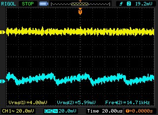
GA PP: 3.3V and -3V Power Supply Noise

GA P4: 3.3V & -3V Power Supply Noise
Analogue Output
The standard test that I’ve been using throughout the development is to feed in a 43.1Hz Sine wave generated from a 1024 value 16 bit LUT. The sampling rate is 44.1kHz, which is generated by Timer 1 to get the closest match.
The spectra and oscilloscope charts below can be directly compared to the testing done with prototype Version P4 and earlier versions of the Goldilocks Analogue.
The below chart shows the sine wave generated at the output of the Op Amp. This is exactly as we would like to see, with no compression of either the 4.096V peak, or the 0V trough.

GA PP: 43Hz Sine Wave – Two Channels – One Channel Inverted
Looking at the spectra generated up to 953Hz it is possible to see harmonics from the Sine Wave, and other low frequency noise.
The spectrum produced by the Goldilocks Analogue shows most distortion is below -70dB, and that the noise floor lies below -100dB. The pre-production sample shows slightly higher noise carriers than the Version P4, but the difference is not substantial.
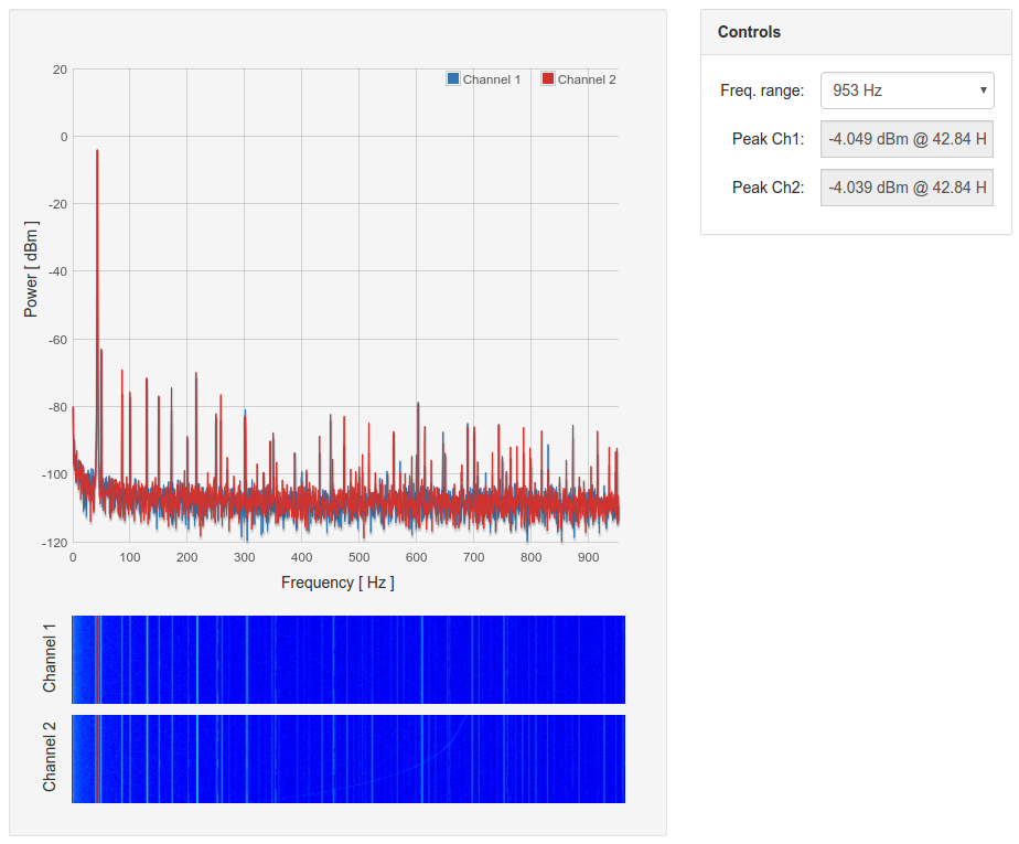
GA PP: 43.1Hz Sine Wave – 953Hz Spectrum
In the spectrum out to 7.6kHz we are looking at the clearly audible range, which is the main use case for the device.
The Goldilocks Analogue has noise carriers out to around 4.5kHz, but they are all below -80dB. After 4.5kHz the only noise remains below -100dB.

GA PP: 43.1Hz Sine Wave – 7k6Hz Spectrum
The spectra out to 61kHz should show a noise carrier generated by the reconstruction frequency of 44.1kHz.
The Goldilocks Analogue shows the spectrum maintains is low noise level below -90dB right out to the end of the audible range, and further out to the reconstruction carrier at 44.1kHz.
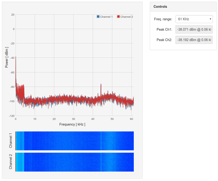
GA PP: 43.1Hz Sine Wave – 61kHz Spectrum
The final spectrum shows the signal out to 976kHz. We’d normally expect to simply see the noise floor, beyond the 44.1kHz reconstruction carrier noise.
The Goldilocks Analogue has a noise carrier at around 210kHz, probably generated by the -3V supply. The noise carrier at 340kHz is generated through the 5V SMPS supply, and is absent when powered by USB socket. Aside from the two carriers mentioned, there is no further noise out to 976kHz.
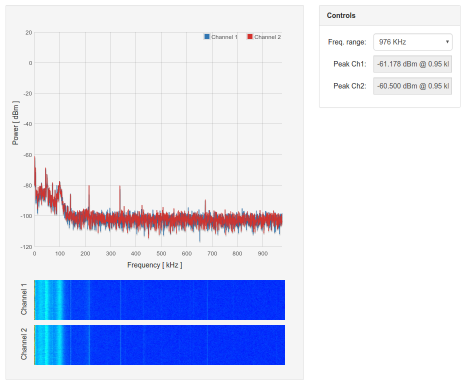
GA PP: 43.1Hz Sine Wave – 976kHz Spectrum
The Pre-production analogue output works as specified, and is essentially identical to the analogue output on the Prototype 4. It can maintain the 72dB SNR required, of which it should theoretically be capable.

Pingback: Yet Another Z80 Project (YAZ180) | feilipu
Pingback: Yet Another Z180 (YAZ180) Project Using Atmega • Tech Projects
Great bblog I enjoyed reading