
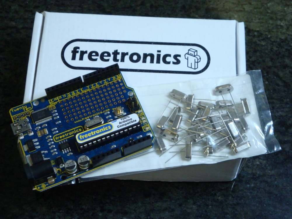
Recently, I picked up a Freetronics 2010 from Little Bird Electronics.

I thought that it would make a nice upgrade to my Dogbot test bed. It uses the same USB connector as Dogbot’s Pololu SVP, so it saves me from keeping different USB cables handy, but is in every way 100% the same as the Arduino Duemilanove that I’ve been using up to now.
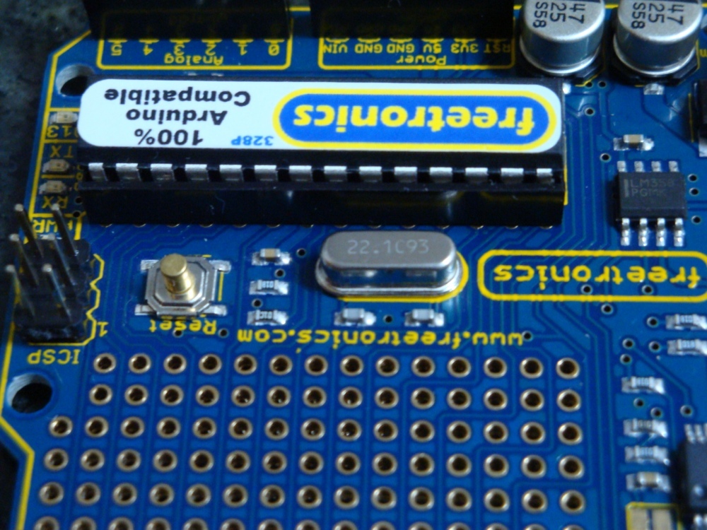
But, everything I own is hacked in some way. So as usual, I thought that the 2010 could be improved, just as I’ve improved the Duemilanove before it, by overclocking it to 22.1184MHz.
Overclocking to 22.1184MHz
So why change the clock frequency to this odd number of 22.1184MHZ, and not to 20MHz which would be in specification?
It turns out that because of the binary and integer world the 2010 and the Duemilanova ATmega328p MCU live in, it is much better have a “nice” binary and integer friendly base frequency. Unfortunately, although 16MHz on a 2010 or Arduino sounds nice, from the point of view of integer programming, clock scaling, and UART interfacing, it is difficult to get clean integer numbers.
A small example.
16MHz clock scaled to 115200baud = 138.888888889 so rounding gives an error term.
20MHz clock scaled to 115200baud = 173.6111111111 so, again, rounding gives an error term.
22.1184MHz clock scaled to 115200baud = 192 with no rounding error.
Also, even though we are getting 16,000,000 instructions per second out of a standard?2010, and that should be enough for any application. I can get 22,118,400 or a 38% improvement for the cost of a few cents. So, why wouldn’t you?
What kind of issues can occur?
Well, over-clocking means that the ATmega328p is out of specification. But, I’m not too worried about pushing specification on this project, as the 328p is certified for an industrial operating temperature range, which is way outside of my operating temperature… There are also unverified reports of AVR ATmegas working successfully up to 32MHz.
In the overall scheme of things, raising the clock frequency on the AVR ATmega328p above specification by 10% to 22.1184MHz is no big deal.
Upgrading Process
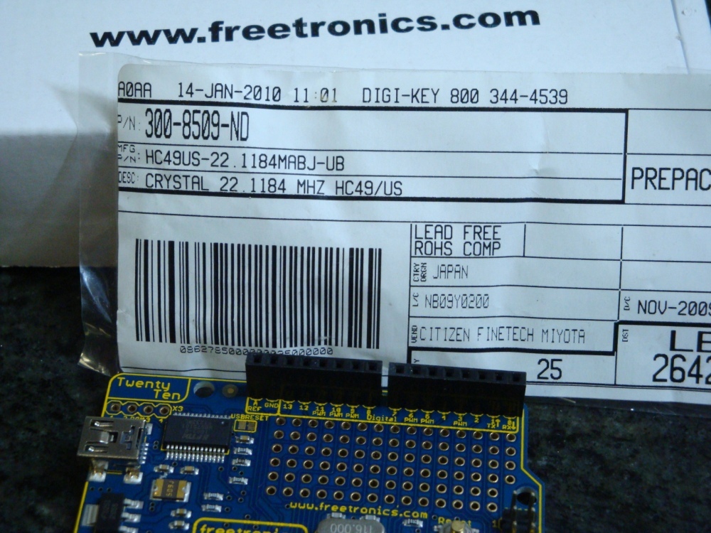
1. Obtain a 22.1184MHz HC49/US crystal from Digikey They’re pretty cheap. Buy a bag in case of accidents.
2. Use a knife tip under the existing 16MHz crystal to give you a lever to pressure it into removal, without burning your fingers. It will get very hot!
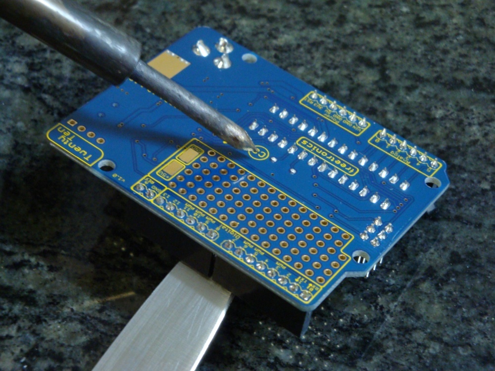
3. Turn over the board and use a soldering iron to heat the joints, whilst leaning on the knife to lever out the 16MHz crystal. Once it is removed, use some solder wick or similar to remove excess solder, and make it easier to insert and solder the new 22.1184MHz crystal.

4. Building a new bootloader. In replacing the crystal, the 2010 is effectively bricked. You can no longer communicate with it using the standard bootloader. It is now running too fast and out of specification for avrdude to communicate with it, so we have to compile and burn a new boot loader before we go any further. I choose to use the Adaboot328 bootloader from Ladyada. It resolves a few known issues with Arduino compatible boards, and is easy to compile.
In the ATmegaBOOT_xx8.c file, change the UART baud rate to 115200, if you use avrdude for programming (if using Arduino IDE, do not change this from 19200). Who has time to wait around these days for 19200 baud, anyway?
/* set the UART baud rate */
#define BAUD_RATE?? 115200
In the Makefile, change the AVR_FREQ value to 22118400L for the adaboot328: TARGET.
adaboot328: TARGET = adaboot328
# Change clock frequency from 16000000L
adaboot328: AVR_FREQ = 22118400L
Then, compile the bootloader, and keep it safe.
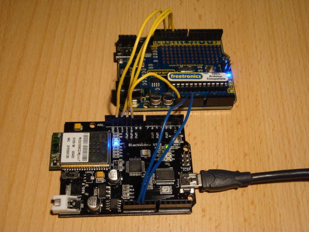
5. Prepare an ISP. There are many alternative ways to do this, and here is not the place to describe the alternatives. Suffice to say that I used the AVRISP method in the Arduino-0018 IDE. I’ve struggled with avrdude (which I otherwise use for everything) as a bootloader ISP. I don’t know why, but I can’t make it work.
It happens that I have a standard Arduino clone available, which I prepare as the AVRISP, by uploading the following sketch File>Examples>ArduinoISP.
6. To be able to use Arduino IDE to burn our special bootloader, you have to replace the standard ATmegaBOOT_168_atmega328.hex bootloader file, found in ~arduino/bootloaders/atmega/ with our newly generated file. And, to make things simple, I just rename or remove the standard one, and replace it with our newly prepared and renamed bootloader with this name
ATmegaBOOT_168_atmega328.hex.
7. Connect our Freetronics 2010 up using the AVRISP connections, described on the Arduino web site. Make sure we have the right board type selected; it should be Duemilanova w/ ATmega328. Then using the Arduino IDE use Tools > Burn Bootloader > w/ Arduino as ISP.
8. Program a sketch using either the Arduino IDE, or using avrdude, remembering that the baudrate is set to 115200. And, enjoy.
Conclusions regarding the Freetronics 2010.
Its a very well designed and produced device, that is 100% compatible with the Arduino Duemilanova. Some advantages are: the mounting holes are slightly larger so cable ties go through nicely, smaller USB connector is more common than the B connector used on Duemilanova, and there’s no solder in the holes for the X3 connector so it is easy to add headers to make it possible to burn its own bootloader (if you want).
It runs my freeRTOS build with no problems, as seen in this demo on my Dogbot test bed with a Robot Electronics Thermopile, and Sharp IR Distance sensor.


